 | English
| Deutsch
FED3+: Torsion Spring: Tolerance for LK0 w/o coil distance

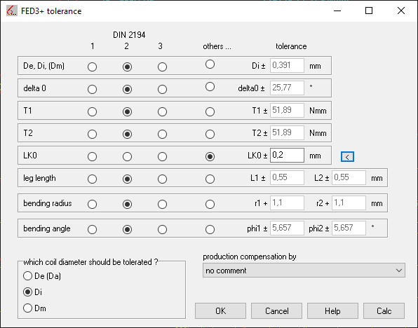
In FED3+, the tolerance according to DIN 2194 for torsion springs with coil spacing is calculated for the spring body length LK0. There is no statement in DIN about the tolerance for torsion springs without a coil spacing, in FED3 + the specified formula is also used for a = 0. However, if the coil ratio Dm/d becomes greater than 10, the tolerance increases exponentially. At Dm/d> 20, the tolerance of LK0 is greater than LK0 itself. If you want to output LK0 without tolerance, go to "Other .." under "Edit\Tolerance" and enter 0. New for FED3 + is now a suggestion button "<". If a = 0 (without coil spacing), a tolerance for LK0 is suggested according to the formula:
A Lk0 (for a=0) = (n + 1) * Ad + Adelta0 / 360 ° * d
With Ad = wire diameter tolerance, Adelta0 = leg angle tolerance, n = number of coils, d = wire diameter.
WN6: Quick3 View
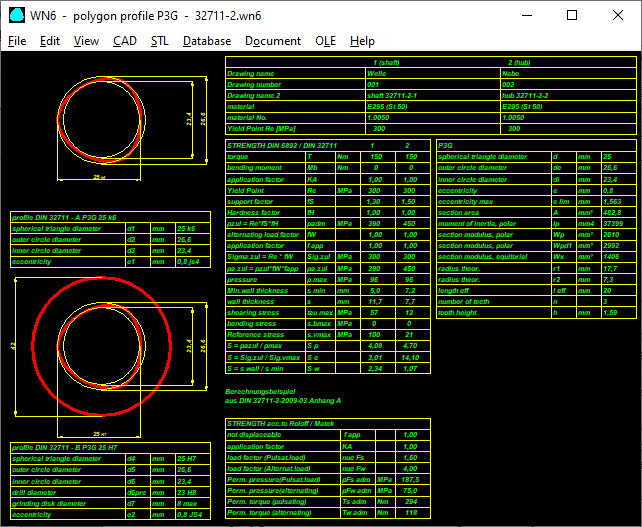
The new Quick3 view contains drawings and tables with the dimensions and strength of the P3G joint.
WN6: Applications for P3G polygon profiles
DIN 32711 states that P3G profiles are not suitable for connections that can be moved lengthways under torque. Why this is so is preceded by an advantage: self-centering of shaft and hub under torque. In fact, the eccentricity (e = tooth height / 2) of the DIN sizes is relatively small, presumably because they can be manufactured with polygon grinding machines. This is why the shaft and hub jam under torsion. This is not so good when the load changes: then the clamp loosens and jams on the other side. Sliding wear, expansion and torsional backlash are the consequences when the direction of rotation is reversed.
In WN6 you can also enter all dimensions directly and enter a greater eccentricity, which reduces the clamping. The hub profile may then no longer be able to be produced with polygon grinding machines; only as a drawn shaft profile, and the hub profile broached, cast, injection-molded or 3D-printed.
However, if you choose the eccentricity too large, you get the effect known from the P4C profile that the polygon curve leaves the harmonic path. Then you have to limit the curve as with the P4C profile with a circular arc.
The greatest possible eccentricity for a harmonic curve is elim = d / 16 = 0.0625 * d1.
WN6: Database extended 110 .. 180 mm
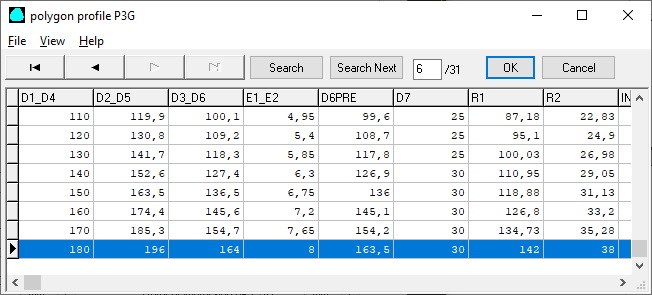
Database p3g.dbf was appended by new sizes of 110mm till 180mm according to DIN 32711-1:2009.
WN7 – Auxiliary age

The auxiliary image for WN7 dimensions has been improved, showing the complete contour and the diameter of the concave circular arc "dre".
WN7: Quick3 View
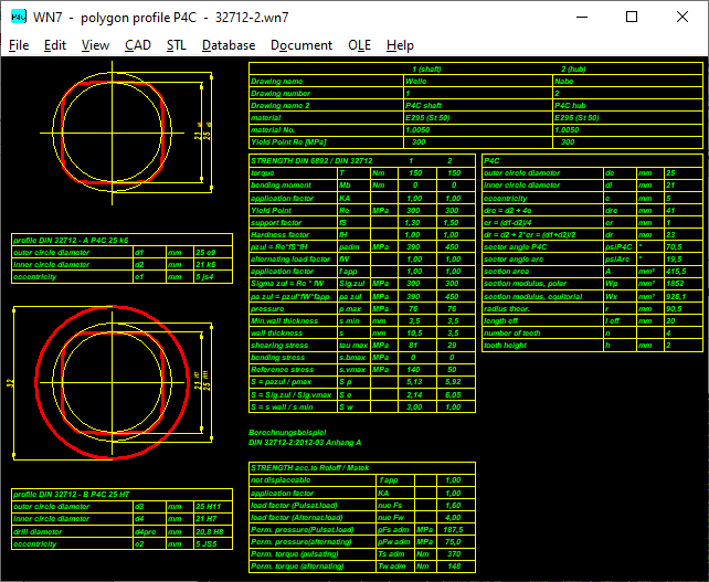
New Quick3 View in WN7 contains drawings and tables with dimensions and strength of P4C joint.
WN7: P4C Database extended 110 .. 180 mm
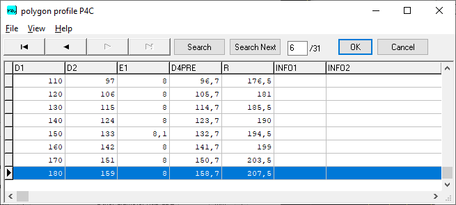
New sizes 110mm until 180mm according to DIN 32712-1:2009 have been added to database p4c.dbf.
WN7: theoretical outer diameter "dre"
For the (theoretical) outer diameter of the continuous trochoid profile, the designation "dre" is introduced in WN7. In DIN 32712 there is already a similar value "dr" as the mean diameter for calculating the surface pressure:
dr = d2 + 2e
dre = d2 + 4e
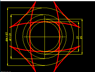

Profile DIN 32712 – P4C 25 with d1=25mm, d2=21mm, e=5mm -> dre=d2+4e=41mm
You can enter d1, d2 and eccentricity e1 for profiles you have defined yourself.
If you want to increase the cylindrical portion, you can decrease d1.

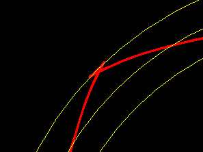
If you set "dre" = d1, the eccentricity becomes e = (d1-d2) / 4 = 1mm. But the eccentricity is still too large for a harmonious profile.
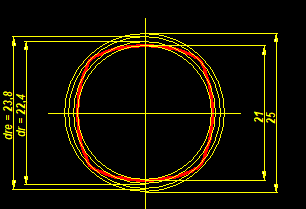
A harmonious "P4G" profile is only obtained when the eccentricity is further reduced to 0.7mm. The outside diameter "dre" is now smaller than the diameter d1 of the original DIN size.
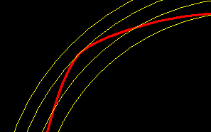
For a harmonic PnG profile, the eccentricity must be smaller than rm / (n²-1). For P4G e <= rm / 15, with rm = 23/2, elim = 0.766 mm.
WN7 – P4C Calculate sector angle

The P4C polygon trochoide profile is cut by an arc of a circle. The proportional angles are now displayed in the Quick3 view: psiP4C with polygon profile and psiarc with circular arc. The two angles add up to 90 degrees.
P3G and P4C standard series
Because the diameter and eccentricity are rounded to whole numbers in the standard series, each profile looks different. Compare a P4C profile with nominal size 14 and nominal size 100!
There is also a publication by Prof. Masoud Ziaei, who examined P3G and P4C connections and derived optimal dimensions from them:
P3G: eccentricity e = 0.036 * dm
P4C: eccentricity e = 0.125 * dm, d2 / d1 = 0.82
With the P4C, dm = d2 + 2 * e. With dm = d2 + 2 * 0.036dm becomes dm = d2 / 0.928 and with d2 = 0.82d1 becomes
dm = 0.82d1 / 0.928 = 0.8836 d1. e = 0.125 * dm = 0.11 * d1. The professor claims, however, that the uniform thickness also for P4C according to DIN 32712 is dm = d1. It therefore remains unclear for the time being how large the optimal eccentricity for P4C according to Ziaei is.
The designations d1 to d6 in DIN 32711 and 32712 are named arbitrarily. With P3C, the nominal size d1 is the mean diameter (constant diameter), with P4C according to DIN 32712, d1 is the outer diameter (which has nothing to do with the polygon).
GEO1+: Polygon profile (P3G)

Polygon-Trochoid-Profiles (P3G) can now also be generated in GEO1+. In addition to the pitch circle diameter and eccentricity, the number of corners and the resolution can also be entered here.
A polygon trochoid with 2 corners results in an ellipse, with 3 corners in P3G. With 4 corners there is a P4C contour, but without limitation by circular arcs. A correct P4C contour can also be loaded into GEO1+: save it in WN7 under "File \ Export DXF" or "CAD \ P4C", then load it into GEO1+ under "File \ Import DXF". In GEO1+ area and area moments are calculated from the sum of the coordinates. A comparison of a P3G profile generated in GEO1+ with data calculated from WN6 shows a good match for cross-sectional area A and moments of area Ip and Ix. The center of gravity is exactly in the zero point. The moment of resistance Wmin is I / rmax with rmax = d2 / 2. With Wx = Ix / d2 / 2 there is good agreement, with Wp = Ip / d2 / 2 there is a deviation of approx. 10% with Wp from DIN 32711.
GEO1+ can also be used to determine the mass moment of inertia of a shaft with a P3G profile.
WN7: Two errors in DIN 32712

A DXF-imported P4C profile from WN7 results in GEO1+ for Wp a higher and for Wx a lower value than according to DIN 32712.
This can be explained by how the section modulus according to DIN 32712 is calculated or, better said, estimated:
Wp = 0.2 * d2³
Wx = 0.15 * d2³
d2 is the smallest diameter on the P4C profile. The section modulus of a P4C profile is definitely greater than that of a shaft with diameter d2:
Wp = pi / 16 (0.196) * d23
Wx = pi / 32 (0.098) * d2³
The polar section modulus of a P4C profile is calculated conservatively according to DIN 32712, but the axial section modulus Wx is calculated too large. So be careful if a P4C shaft is subjected to bending stress! Save the P4C contour in WN7 as a DXF file and load it with GEO1+. GEO1+ then calculates the axial moment of area 2nd order Iz. If the P4C shaft rests on the polygon trochoide contour, Wx = Ix / (d2/2). If the P4C shaft rests on the circular contour, Wx = Ix / (d1/2).
In WN7, the approximate calculation of Wx has been changed to Wx = 0.1 * d2³, which deviates from DIN 32712
There is an even more serious mistake when calculating the surface pressure according to DIN 32712. Proof: Make the eccentricity very large (for a flat curve), then the surface pressure p approaches 0. Because dr = d2 + 2e is specified. In contrast to P3G, you can make the eccentricity as large as you want in P4C (eccentricity infinite results in a polygon cut with a circle). Presumably dr = d2 + 2*er. Because dr should be the mean diameter dm = Rm / 2 (equivalent to d1 for P3G) dr = (d1 + d2) / 2 = d2 + 2 * er = d1-2 * er. In WN7, contrary to DIN 32712, "dr = d2 + 2 * er" will be used instead of "dr = d2 + 2 * e".
Applied to the calculation example in DIN 32712-2: 2012 Appendix A, "dr" is then 23mm instead of 31mm, which means that the surface pressure is p = 80 MPa instead of 51.57 MPa.
An alternative calculation p = F / A with F = Mt / (dm/2) and area "A = tooth height * width * number of teeth" gives an even higher value of 94 N/mm². Almost twice as big as according to DIN!
WN6: Error in DIN 32711
There is also a small error in DIN 32711: the rather complicated formula for calculating the polar moment of resistance Wp is incorrect. Proof: Set eccentricity e = 0, then the values of Ip, Wp, Wx, A must agree with the values of a circular cross-section.
The simple formula Wp = 2 * Ip / d1 would be more correct
The deviation is not serious, so the DIN calculation in WN6 is retained for the time being. In addition, the section modulus "Wpd1 = 2 * Ip / d1" is calculated and printed out.
In any case, the section modulus of the P3G profile is only used to calculate the shear and bending stress of solid shafts. The section modulus of a circular ring is used for the hub or hollow shaft.
The calculation of the minimum wall thickness according to DIN 32711 and 32712 is at least questionable. For P3G connections the minimum wall thickness is twice as great as for P4C connections.
Perhaps it is believed that P3G is used for interference fits and P4C is used for sliding connections.
WN13: New software for PnG joints

Soon there will be a new calculation program WN13 for PnG connections with 2, 3, 4, 5, 6, n corners (P2G, P3G, P4G, P5G, PnG) where you can freely enter the constant diameter and eccentricity. The maximum eccentricity is elim = d / (2 * (n²-1)). Polygonal shaft connections could become the preferred shaft-hub connection for non-cutting machine elements.
WN14: New software for PnC joints
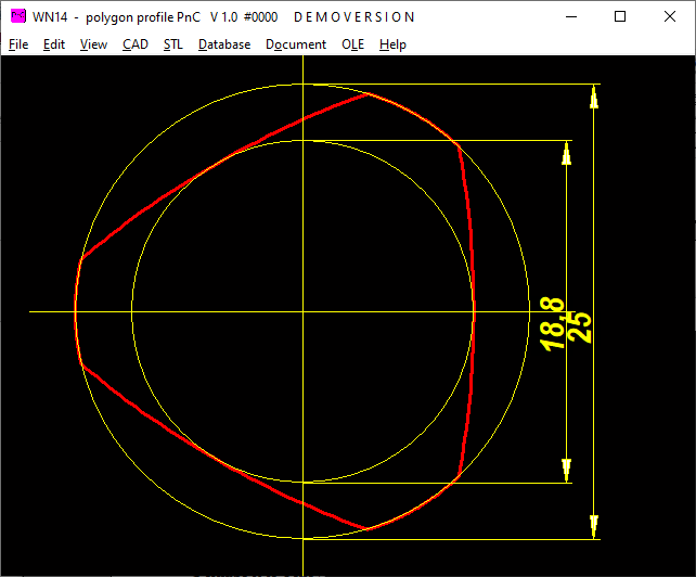
Soon there will also be a new calculation program WN14 for PnC connections with truncated polygon-trochoid profiles such as P4C, but also with 2,3,5,6 corners.
The PnC profile is also interesting for shafts that can accommodate both cylindrical and PnC machine elements, e.g. rolling bearings, gears and pulleys on a continuous shaft.
TR1: Polygon-Trochoid Profil (P3G)
The polygon trochoidal shaft was added to the profile database for girder calculation. This allows shafts with a P3G profile to be calculated as a girder. However, only on tension / compression and bending, not on torsion. The number of corners can be entered. With 2 corners there is an ellipse. The more corners, the smaller the eccentricity must be. Otherwise there is the known effect of P4C profiles of limiting the usable profile by means of a circular arc. In TR1, there is also the option of importing any cross-section consisting of one polyline as a DXF file.
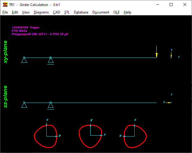
Under "View \ Profile with stress and bending", the bending stress at each point of the profile is displayed, as well as the deflection at the specified x-coordinate (yellow contour).

GEO4: Import DXF
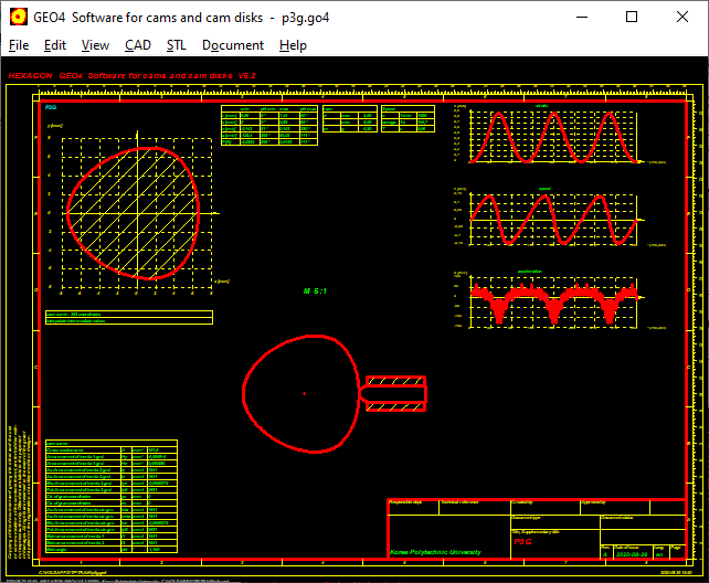
Using Import DXF option, you can load polygon profiles from WN6 or GEO1+ into GEO4 as P3G cam or cam shaft.
ZAR4: Import DXF

Using "Import DXF" option, you can load polygon profile of WN6 or GEO1+ into ZAR4 as P3G gear.
ZAR1+, ZARXP, ZAR1W, ZAR5, ZAR7, ZAR8: Tooth root trochoide and undercut

For very strongly undercut gears (e.g. alfa = 15 ° and x = -1.3), the root rounding trochoid at the transition to the involute was not drawn cleanly. In this unusual gear, the pitch circle diameter is outside the toothing, and the undercut area with the fillet is larger than the involute. Such gears are now also drawn continuously if the starting angle of the root fillet is enlarged (+2pi instead of +0pi) under "CAD \ Settings \ Draw tooth root curve ?".


ZAR1 +, ZAR5, ZAR7, ZAR8: Bore P3G, P4C, P4C, P3C, P6G, square, hexagon
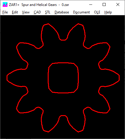
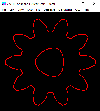
There are now various alternatives to a round hole for the production of gears with a 3D printer: flattened, square, hexagonal, P3G, P4C, P4G, P6G, P3C. In addition, a keyway and a sine wave. You do not have to enter any further dimensions, standard values are used. P3G data, for example, are d1 = dB, e2 = 0.04 dB (d5 = dB + e2, d6 = dB-e2). You can select and enter the options under "CAD \ Gear Wheels":
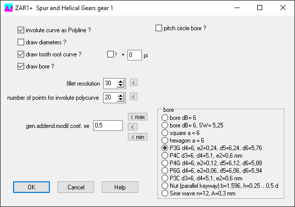
Besides P3G and P4C, there are also P3C, P4G, P6G, and round sine wave.


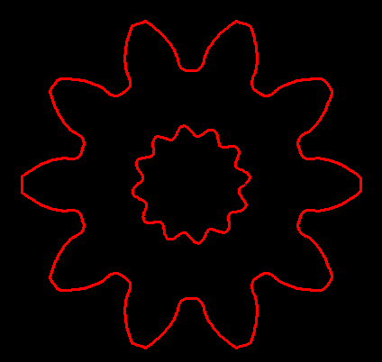
ZAR1 + 3+ 4 5 7 8: Manufacture gears with a 3D printer
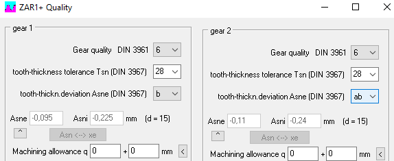
Straight-toothed gears can easily be produced using 3D printing. In the case of helical gears, the tooth flanks should then be smoothed, because in 3D printing the tooth incline results in a step function (step height = layer thickness).Because of the larger tolerances in 3D printing of gears made of PLA or ABS, the backlash must be increased so that the model gears also run. Under "Edit \ Quality" select a tolerance field for large backlash, e.g. b 28 for gears made of PLA or ABS. No machining allowance (0).
To shorten the printing time, you can enlarge the bore diameter. With helical gears you should configure the layer thickness "zslice" under "File \ Settings \ CAD". This should be the same as the layer thickness set on the 3D printer. Caution: do not set it unnecessarily small, halving zslice doubles the STL file size.

Menu "STL Gear wheel":
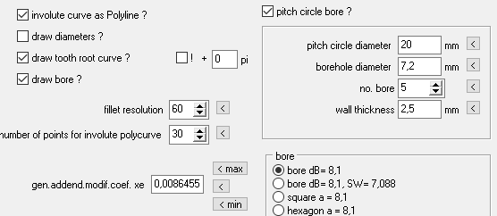
Involute as a polyline: regardless of whether it is a polyline or a line.
Draw in diameter: no, only the gear contour belongs in the STL file
Draw root fillets: yes, as in the drawing
Draw bore: yes, otherwise the gear will come on a solid shaft
Resolution of fillet and involute: as in the drawing
Generated profile shift factor: "<" button for tolerance center or "min" "max" with direct effect on the backlash.
Pitch circle: a pitch circle with holes can be used to attach a gear or ring gear, or simply to save material.

Rack: For a rack, enter a large number of teeth (-2000) and a small backlash (independent of the pitch circle), then enter the number of teeth under "STL \ Sector \ Gear 2".
ZAR1 + 5 7 8: Recommended values for number of teeth measured and ball diameter

The suggested values with the "<" button were calculated from the profile shift factor xemin, whereas the input values were checked with tolerance center (xemin + xemax) / 2. In the case of large tooth flank tolerances, the suggested values for the maximum value of xe result in different numbers of measuring teeth and ball diameters than for the minimum value with a difference of more than 30%. For some borderline cases there was therefore the curious case that a warning "k measure!" was displayed even though the default value was used. The mean profile shift factor calculated from the tooth thickness dimensions is now used for all suggested values. I would like to thank Jong-Gak Kim from Pion for pointing this out.
Virus scanner false positive
Some virus scanners (for computer viruses) report warnings for executable files that they are not yet aware of. Or which you already know, but which differ slightly. This applies to every HEXAGON executable file: Every exe file is different and individual because it contains the name of the licensee. It is different with most software providers; every customer works with the same exe file. This makes it easy for virus companies like Symantec to catalog the files and then simply compare the exe file with the stored characteristics: If there are discrepancies, it could be a file that has been mutated by computer viruses. There are always differences with HEXAGON software: every wfed1.exe is different. This is suspicious for virus scanners: they may not find a virus, but they detect an allegedly mutated file and issue a warning. At Symantec, the warning is called "WS.Reputation.1". You can ignore this warning.
Corona viruses on a world tour
A Corona virus does not travel two meters without outside help. Viruses are transmitted through travelers. Corona viruses travel around the world. In spring they said goodbye from Europe to South America, where summer is winter. Continuing via North America and Russia, they return to Europe for the flu season. Only in China are the viruses not returning: China has canceled all international flights except for cargo flights and a few return flights for Chinese overseas students and closed all borders so that travelers do not bring the corona pandemic back. Free travel for goods, but entry stop for people and animals. With success: in the huge empire of China there are fewer new coronavirus infections in August 2020 than in the small Free State of Bavaria. If corona sufferers were successfully isolated 6 months ago, the healthy are now isolated. While other countries are spending billions on corona consequences, economic growth is also expected for China in 2020. In China you don't need a mask anymore. They can all be exported. To Europe, that is where the new mask fanatics sit. There even an EU commissioner has to resign because he once forgot his mask.