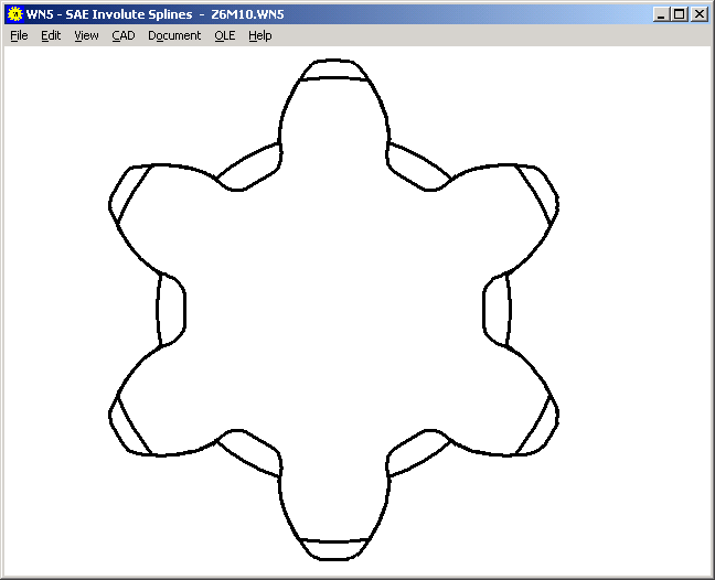
WN5 - Software for Involute Splines to ANSI B92.2M

Two months ago we released WN4 software for calculation of involute splines to ANSI B92.1.
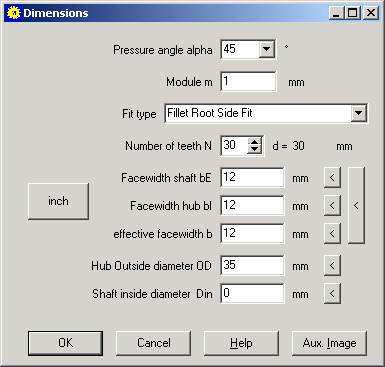
Now we can offer the new WN5 software for metric involute splines according to ANSI B92.2M
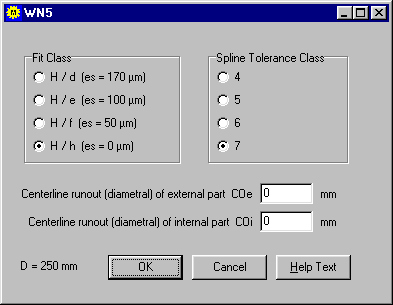
The signs used for geometric dimeensions differ between ANSI B92.1, ANSI B92.2M and DIN/ISO. WN5 calculates stresses and safety factors according to SAE Involute Spline Design Guide.
Comparison of Designation to ANSI B92.1, ANSI B92.2 and DIN/ISO
|
ANSI B92.1 |
ANSI B92.2M |
DIN 5480 |
|
Do |
DEE |
da1 |
|
Di |
DII |
da2 |
|
Dre |
DIE |
df1 |
|
Dri |
DEI |
df2 |
|
Dref |
D |
d |
|
s |
E |
en |
|
t |
S |
sn |
|
cF |
CF |
kmn |
|
DFi |
DFI |
da01 |
|
DFe |
DFE |
da02 |
DIN/ISO uses negative signs for internal splines. Major diameter and minor diameter are created by addendum and dedendum of tool. ANSI uses no negative signs, so major diameter and minor diameter designation is reversed for the internal spline.

FED1+, FED2+, FED5, FED6, FED7 – Relaxation
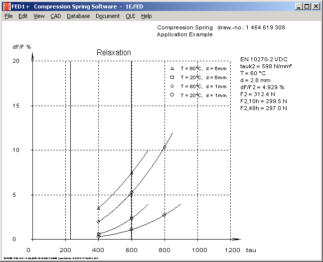
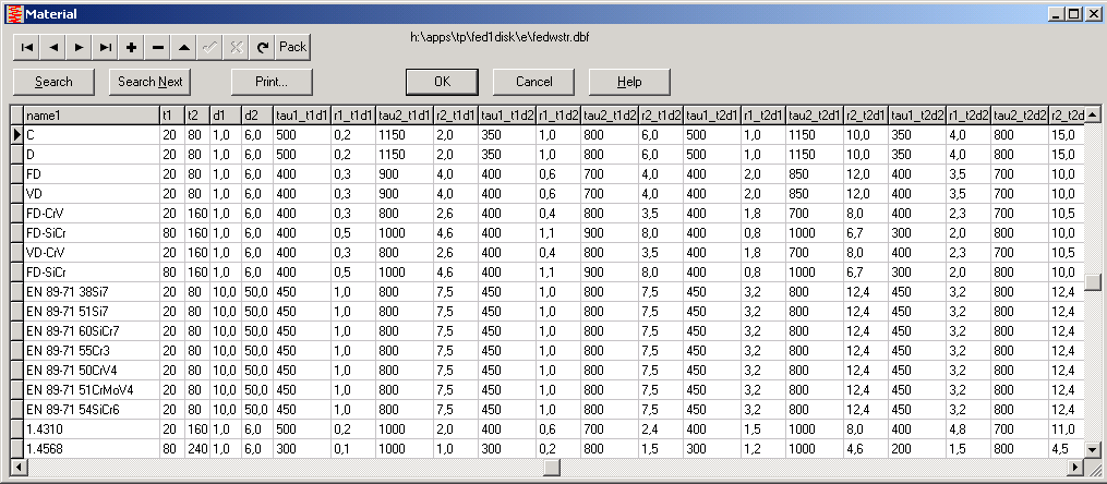
Relaxation of springs can now be calculated by our software for compression springs and extension springs. Caused by high stress and high temperature, spring relaxes and spring force reduces by the time. Parameters for relaxation are stored at the "fedwstr.dbf" database, that may be appended and modified by the user. The parameters are: relaxation in per cent after 48 hours for two shear stress values, two temperatures and two wire diameters.
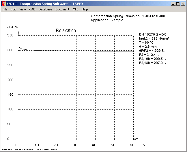
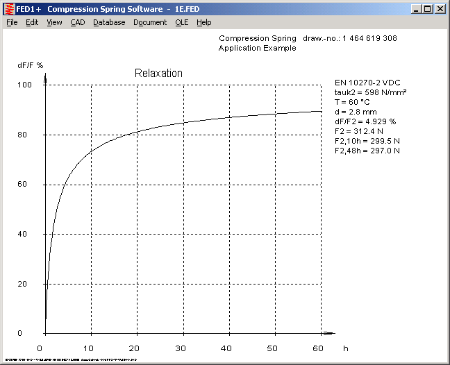
The software calculates relaxation for spring load F2 and draws diagrams of relaxation dependant from stress, temperature and wire diameter, or diagrams of relaxation rate and relexation of spring load F2 during 60 hours.
FED5, FED6 - Hide Warnings
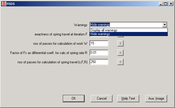
Warnings because of non-recommended coil ratio, risk of setting, buckling, override of permissible shear stress at block length and usable length can be omitted by option at "Edit->Calculation Method".
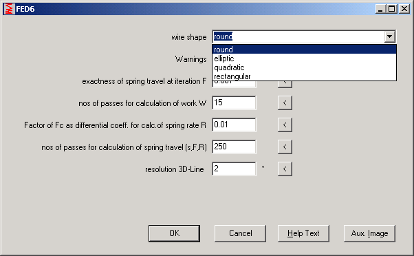
FED6 – Rectangular and Elliptic Wire
Nonlinear cylindrical compression springs of rectangulare, square or elliptic wire section can now be calculated with FED6.
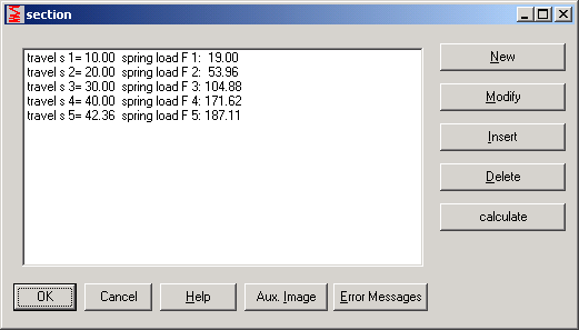
FED6 - Input Characteristic curve of spring
FED6 calculates a nonlinear compression spring from any progressive load curve. The procedure to use this option is as follows: Create a draft of the progressive curve you want to have for the spring. If your x-axis scales the spring length L, then add the spring travel s (s=0 starts at the intersection point with the x-axis, at F=0). Now enter the points of the spring curve at "Edit->Char.Line", then "New". After you entered all points, click into the "Calculate" button and enter coil diameter and wire diameter (0=suggest). Let L1, L2, Lx calculate by FED6 for now. Then exter spring length L0 (=Li + si). Leave block length Lc unchanged, else additional end coils will be added to the spring. FED6 now calculates the final part of the characterisr´tic spring curve, and adds a new section to the spring section array. For later re-calculations with other values, don't forget to delete the last spring section before entering new values for the spring properties.
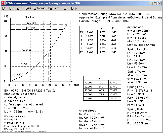
FED1+, FED2+, FED5, FED6, FED7 - F-L-Diagram
Characteristic line of spring is a function of the spring travel. Alternative, you can draw a diagram with spring length L (=L0 - s) on the x-axis.
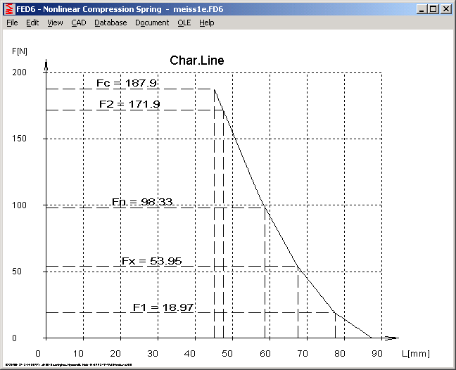
Characteristic line of spring as function of spring length
WST1 - Metric or Imperial Units
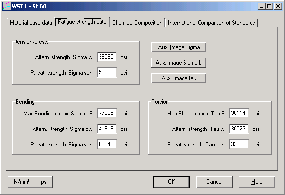
WST1 allows you to switch between metric and imperial units at all input windows and output diagrams.
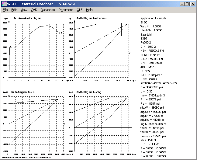
WST1- Quick-Output with English units
SR1 - Tolerance for Tightening Torque and Friction Coefficients
At the previous info letter No. 64 was described how to calculate minimum and average value of tightening torque. This was not correct, because friction deviations were not considered. The factor
alpha A = FM / FMminhas to consider both, the tolerance of the tightening tool as well as the deviation of the friction coefficients.
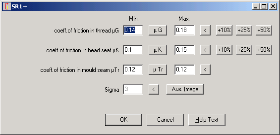
The new version of SR1 and SR1+ allows you to enter a min and a max value for the friction coefficient. The software calculates a minimum tightening torque MA min that considers tolerances of tightening tool and friction.
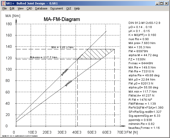
A new MA-FM-Diagram is available at SR1+. Clamp load is scaled on the x-axis, with FM and FM/alphaA. The line µmin (minimum friction) crosses the tightening torque at MA (FM) and MA/alphaA (FM/alphaA). At FM/alphaA one can get the minimum torque MAmin from the intersection point with the µmax line. Tolerance zone is hatched at the diagram.
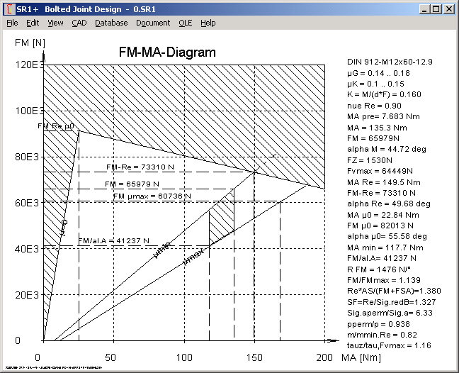
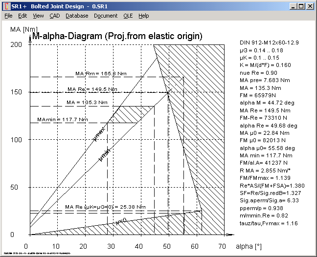
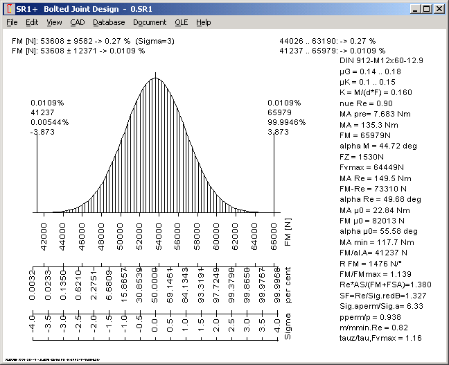
Due to consideration of friction tolerances, the remaining permissible torque deviation for the tightening tool is reduced substantially. At the above example, the permissible tolerance for the tightening torque was reduced from MA - MA/alphaA= 48 Nm to MA - Mamin = 21.5 Nm. SR1+ calculates tolerances and scrap rate for statistical addition of the normal-ditributed tolerances (Gaussian bell-shape curve)
Tol FM tot ˛ = Tol FM µ ˛ + Tol FM MA ˛
Distribution curve and results are displayed at "View->FM Statist.".
FED10 – Calculation of Leaf Springs
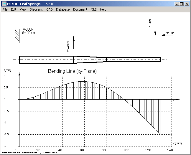
In short time we can offer a software for calculation of leaf springs.
HEXAMENU and BMPVIEW
Some inconveniences have been noticed at the freeware tools HEXAMENU and BMPVIEW. At HEXAMENU, the backgound picture hexagon.jpg must be copied manually, or you have to chooses another background picture. The cfg files created by the HEXAGON programs have to be copied to the HEXAMENU folder or to "c:\hexagon", else the configuration data cannot be loaded.
The BMPVIEW setup program does not install the example pictures. If you want to convert a graphic from the clipboard to JPG format, you first have to save it as BMP file.
Help Menu Links to HEXAGON-Homepage and E-Mail Draft
If you installed a web browser, you can directly send an email or access to www.hexagon.de at Help Menu.
Training program 2001
At March 2001 we offer seminars for calculation of gears and springs, see info at Seminarplan.