English
Deutsch
Info Letter No. 50 - July/August 1998
Copyright by HEXAGON Software 1998
NT Versions
We now have 32-bit versions of our programs HPGLVIEW, HPGL Manager,
DXF Manager and FED1+. They differ to the old Windows versions in
their window arrangement and user elements. Long file and directory
names are now supported. You can now save the documents under the part
number, even when this is longer than 8 characters. In addition, the
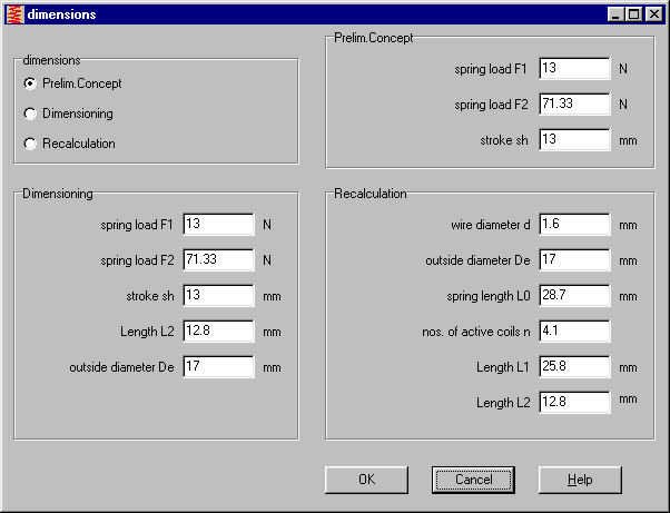
window interface has been improved. For example, if you wish to
calculate a new spring with FED1+ under "File->New", there are now
options for pre-dimensioning, dimensioning and recalculation. You can
either select the spring forces and installation dimension form to
calculate the necessary spring, or you can enter the dimensions of the
spring for the recalculation.
 When you save standard settings for the spring calculation under the
file name "NULL", the default values are loaded each time you start
the program.
Graphics, drawings and diagrams under the 32-bit versions are printed
out in higher quality than with the 16-bit versions.
FED1+ Deviations and Tolerances
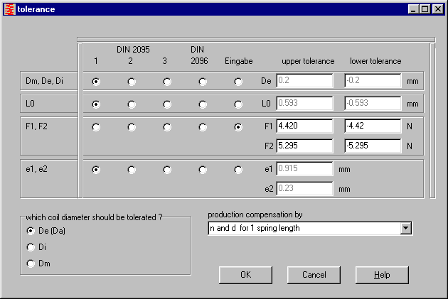
When entering the quality and tolerances, the
deviations are shown in mm's in the input window on the right.
This allows you to see immediately the effects of changing the
quality class. When the quality class is changed, the deviations are
immediately recalculated. By clicking on the "Input", you can
enter the deviation manually.
NT Data base
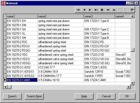
With the integrated browse window it is now much easier to
append or change materials, spring or calculation data in the data base.
NT Configuration
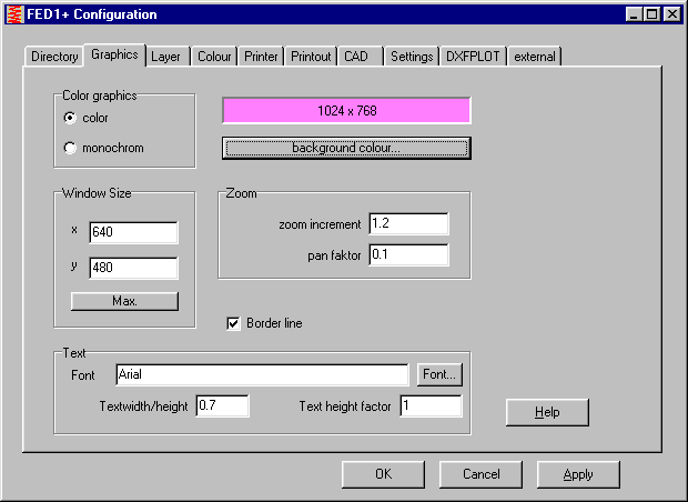
Configuration has now also been made easier and more user friendly.
Directories and files, as well as text fonts and colours can be
selected instead of entered. You can now select a font height factor
for text to be shown in diagrams and drawings, as well as a font width
factor. The background colour can be selected from the available
Windows palette.
HPGLMAN / DXFMAN - Configuration
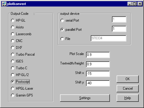
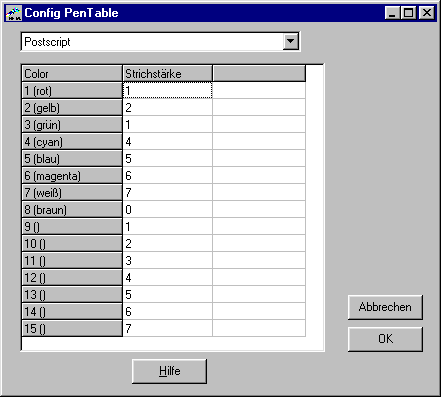 The configuration for the pens in the HPGL and DXF Managers has been
improved. You can now configure the colour numbers for the DXF
Manager, and the pen numbers for the HPGL Manager. When outputting as
DXF or IGES files, different colours can be defined, for postscript
different line thicknesses, and for CNC code different tool numbers
and advancement increments.
HPGLMAN / DXFMAN NT
The 32-bit versions of the HPGL Manager, DXF Manager and HPGLVIEW are
available now in German and English. FED1+ will be available from 15
September 1998. By the end of the year, all Hexagon programs should
be available as 32-bit versions. The 16-bit and DOS versions will
continue to be available. When converting to the new 32-bit versions
all files and data bases from the old versions can be used.
 The price for a disk-update to the new versions is 60DM per program
(120DM when converting from MS-DOS). The prerequisite for an update,
is that the licence contract was previously filled out and already
sent back.
HPGL Manager Full Circle Conversion
Arcs with a starting angle of 0 degrees and an end angle of 360
degrees are given out as a "Circle" when converting to DXF.
DXFMAN, GEO1 - Unix Files
The end of the line is marked in PC text files with the characters
#13#10 (Carriage Return, Line Feed). In Unix system files only the
character 10 is used. This has caused difficulties when loading files
to DXF from CATIA. DXFMAN and GEO1 have been modified so that Unix
files can also be loaded without problem. I would like to thank Mr
Baumgart of Porsche Engineering, Bietingen-Bissingen, Germany for this
information and test files.
WL1/WL1+ Shaft Geometry from DXF Files
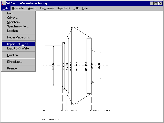 According to customer wishes, the shaft calculation program has had
an import function added for DXF files. The shaft geometry no longer
needs to be entered, but can be taken from CAD. Before this the
shaft should be cut out of the drawing, all other parts, views,
dimensions, drawing header, etc., should be deleted. The middle line
of the shaft is either on, or parallel to the x-axis, the
y-coordinates are required by WL1+. I would like to thank Mr Listner
of Daimler-Benz, Untertrkheim, Germany for this suggestion.
WL1+ Calculation of Spur Gear Load
You should only use this input when you wish to calculate a shaft with
more than two gear steps, otherwise you should preferably use the
input under "Complex Load". Here any number of additional gear steps
can be calculated. WL1+ calculates the resulting forces, path load
and factors. If you wish to make changes, you should first delete the
old values. In the newest version, the gear values are reset to zero
when you start input to prevent the impression that the values already
entered in "complex load" need to be calculated.
WL1 - Tension Stress with Hollow Shafts
With hollow shafts the calculation of tension and pressure stresses
due to axial forces was not taking the inner diameter of the shaft
into account, the program was calculating with the cross-section of a
solid shaft. This only occurs with load due to axial forces, the
values for the stresses from shearing loads, path loads and bending
and torque are calculated correctly. Please check to see if this
error occurs with your version. If you have registered your program
by sending the licence contract back, you can request a free update.
Please send the WL1 program disks back to us. I would like to thank
Mr Pppinghaus of Winhaus, Wahlhausen, Germany for bringing this to my
attention.
2h3>TR1 - Tension/Pressure
When the cross-section surface A has a negative mathematical sign, the
tension and pressure stresses occur from the axial forces with a
reversed mathematical sign (this occurs when the geometry is
entered in a mathematically negative direction). The new version of
TR1 calculates with the absolute value, so that tension stresses have
a positive sign and pressure stresses have a negative sign.
TR1 - Reference Stress
A diagram with the reference stress over the x-axis has been added.
The reference stress from bending and tension stress is obtained by
simply adding Sigma b to Sigma z.
ZAR1+ Planetary Gear
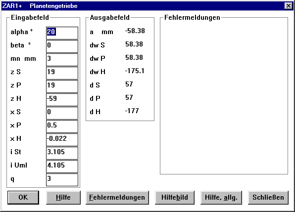 For the preliminary concept of planetary steps the faxtor xS for
the sun gear is recalculated when entering the addendum modification
coefficient xH of the hollow gear.
ZAR1+ Addendum Reduction
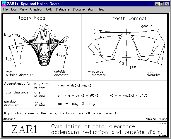 For the standard geometry, where you can either enter clearance,
addendum reduction or outside diameter, the program now also allows a
negative clearance of -0,25mm. However, the error message "kmn<0!"
will appear. I would like to thank Mr Brutschin of
Rotzler in Steinen, Germany for this improvement suggestion.
ZAR1+ Tooth Forces
The tangential force due to the transfered torque does not apply to
just one point, but is really a path load which is distributed over
the whole application path. The greatest force occurs at the
application point (operating pitch) and fills out both sides. When
several teeth are applied at the same time, it becomes even more
difficult. For the load-bearing capacity calculation of the teeth the
tangential force in the generated pitch is used. The tangential force
in the operating pitch is used for the calculation of shafts and
bearing loads. Until now, the tangential force of the generated
pitch, and the resulting axial, radial and normal forces were
calculated. With the new version the tangential forces Ft (generated
pitch) and Ftw (operating pitch) are printed out, normal and radial
forces are calculated from Ftw and atw. Ft = 2 * T1 / d1
Ftw = 2 * T1 / dw
Fx = Ftw * tan ß
Fr = Ftw * tan atw
Fn = Ftw / cos atw
Until now, Fx, Fr and Fn with Ft instead of Ftw were calculated. With
addendum modification and a smaller number of teeth the error rate was
up to 20%. I would like to thank Mr Langenberg of Deutsche
Bergbautechnik in Lnen, Germany for drawing this to my
attention.
Theories for Calculation of Toothed Shafts and Hubs with ZAR1
Due to changes in tooth height, ZAR1+ can also be used
to calculate the geometry of toothed shafts and hubs in accordance with
DIN 5480. In the directory TRAIN you will find a sample file
STECKVZ.ZAR. Under "Edit->Quality" the deviations Asne and Asni can
be entered freely. This allows calculation of span
measurement for any tolerance.
SR1 - Minimum Screw-in Depth
On the internet
"www.hexagon.de/dose/dose1.htm"
you will find a publication by Mr Dose (Dipl.Engineer, G.F.) with the
methods he developed for calculating the minimum screw-in depth for
bolted joints as they are shown in SR1. The correctness of the
calculation has been proven in tests. I would like to thank Mr Dose
for providing me with the documentation.
SR1 - Calculation after "Quit"
Until now the program has not carried out a new calculation when you
leave input with "Quit". The new version carries out a calculation
with the newly entered values. For this suggestion I would like to
thank Professor Zammert of the Polytechnic in Esslingen, Germany.
Spring Material VD-SiCr
The shearing modulus has been changed from 81500 N/mmı N/mmı (in
accordance with Garphyttan Information from 1988 for Oteva 70) to
79500 N/mmı (in accordance with the Bosch standard). A shearing
modulus G of 79500 N/mmı is shown in the current material data page
(1998) by Garphyttan. I would like to thank Haldex in Duesseldorf,
Germany for allowing us to use the data pages.
FED2+ Pre-Stress
Under dimensioning, recalculation and pre-dimensioning the largest
possible sign > can be entered for F0, then the greatest possible
pre-stress for spring steel wire in accordance with DIN 17223 is
calculated. I would like to thank Mr Michel Uancea of Vanhulen,
Herstal, Belgium for providing me with the calculation formula.
Seminar in Autumn 1998
Gearing and Gear Calculation (2 days)
Date: 14-15 October 1998
Instructor: Dr. Körner
Course cost: 1000,- DM
Vibration and Noise Behaviour in Gears
Date: 16 October 1998
Instructor: Dr. Mueller
Course cost: 500,- DM
Spring Calculation
Instructors: Schnitzer, Zammert
Date: 20 October 1998
Course cost: 500,- DM
Certification in accordance with DIN ISO 9001
Date: 13 October 1998
Instructor: Körner
Course cost: 400,- DM
Demo Version HPGLVIEW NT
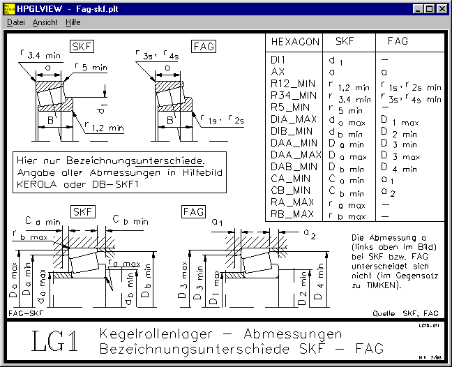
There is a new demo version of the 32-bit HPGLVIEW. You can
download it from the internet " www.hexagon.de/zip/hpvi32_d.zip.
With HPGLVIEW you can for example, display and print out all the
auxiliary pictures available in all of our programs (.plt files).
Price List |
Orders |
E-Mail |
Homepage


