 | English
| Deutsch
SR1/SR1+: Calculation method "washer dwa=dw+1.6*hs" redundant

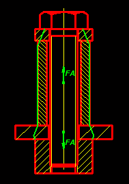
According to VDI 2230, when using a washer, the area for calculating the permissible surface pressure for the subsequent clamping plate can be calculated with the outside diameter dwa=dw+1.6*hs. "hs" is the height of the washer. Thus, a deformation cone of arctan(1.6/2) = 39° is always assumed for the washer. However, if the subsequent clamping plate has a smaller outer diameter than the washer, the deformation cone becomes negative. In this case, the formula does not apply, SR1 had calculated too little surface pressure with dwa of the washer. That has been corrected. There were the following changes:
- Edit\Calculation method: "washer dwa=dw+1.6hs" no longer set at program start.
- "washer dwa=dw+1.6hs" not applied if diameter of subsequent clamping plate is smaller than dwa washer.
- "washer dwa=dw+1.6hs" for washer under the nut only used with DSV (no longer with "ESV+dw").
How does SR1 know if the first and last clamp plates are washers? If the thickness is less than 0.5*inner diameter, the washer option is applied. Unfortunately, a sheet metal is also calculated as a washer. It is better to switch off this option, then the surface pressure is calculated from the determined dimensions of the deformation cone. That should be more accurate than "dwa=dw+1.6hs".
This option will no longer be set in the program when the program starts. If you also want to do this in your version of SR1 (without updating), go to "Edit\Calculation method", uncheck "washer dwa=dw+1.6hs", then "File\\Save as" file name "NULL" . If a null.sr1 file is present, it will be loaded automatically when the program starts.
As a precaution, please check your calculations with more than 2 clamping plates or if the washers are followed by thin spacer sleeves with/without washer option.

FED5: Pitch Po and Pu as well as coil distances aWo and aWu printed
       ----------------------------------------------------------------------
       Pitch upper                       Po       mm              4,56
       ----------------------------------------------------------------------
       Pitch lower                       Pu       mm              9,11
       ----------------------------------------------------------------------
       Coil space upper                  aWo      mm              3,56
       ----------------------------------------------------------------------
       Coil space lower                  aWu      mm              8,11
       ----------------------------------------------------------------------
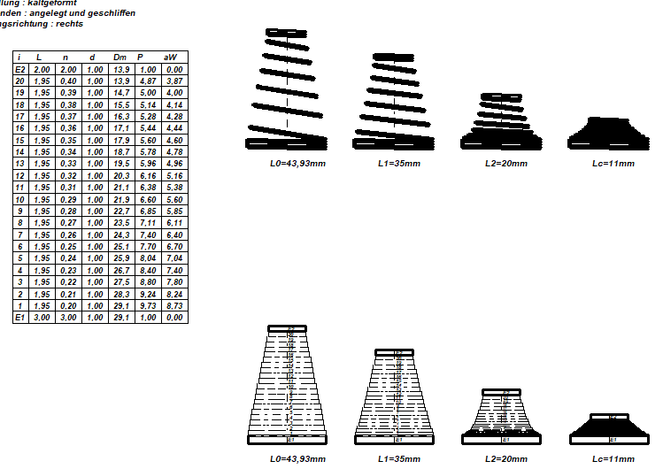
The pitch P0 of the unloaded spring Po (above) and Pu (below) as well as the coil spacing aWo and aWu (aW = P – d) are printed out in the printout as well as in Quick3 and Quick4 views if a pitch ratio Po/Pu unequal 1 was entered .

FED5: Export to FED7
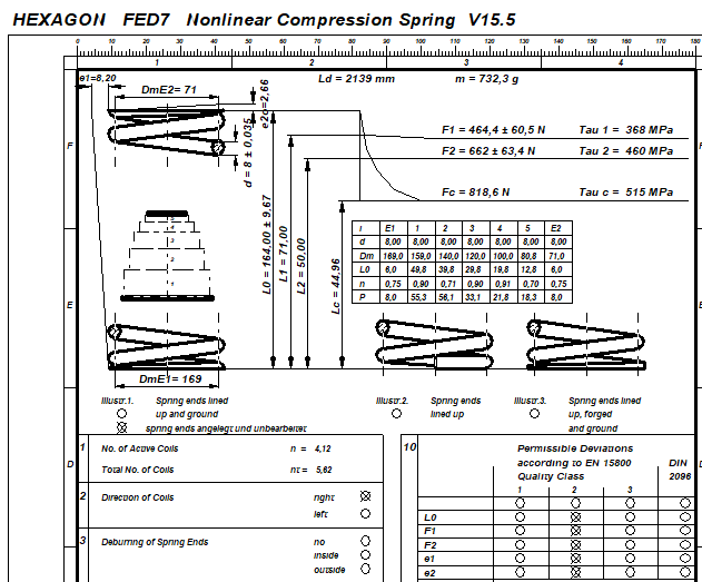
In FED5 there is now an export function that generates an fd7 file. This can be opened directly with FED7. Before doing so, you will be asked how many cylindrical winding sections the conical spring should be divided into. Please note: Because FED7 calculates the winding sections as a series connection of cylindrical compression springs, the axial application of the windings is not taken into account. The calculated spring lengths Lc and L0 are larger in FED7 than in FED5.

FED7 Production Drawing: Coil diameter dimensions
The mean coil diameters at both ends of the spring are now dimensioned in the production drawing. Because coil diameters vary in FED7, a grade for dimensional tolerances is not applicable here and has been removed from the table.

ZM1: Correction sprocket profile
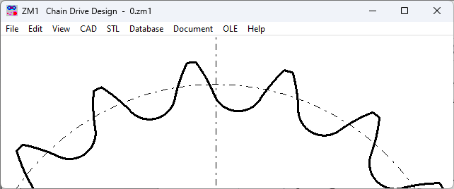
In the sprocket profile of the right flank, a straight line was accidentally drawn instead of an arc in ZM1 Version 3.0. This has been corrected.
