 | English
| Deutsch
FED1+, FED5, FED6, FED7, FED17: "Set Spring" Options in Production Drawing

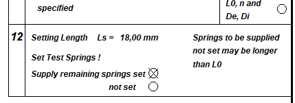
Under "Edit\Production drawing" you can now click whether the texts "Set test springs!" and "Springs to be supplied not set may be longer than L0" should be displayed. If the springs are not set, you can hide the text.


WL1+, TR1: Input Material Number
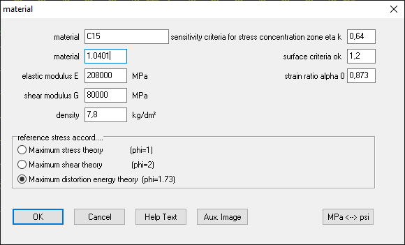
The entry of the material number was added to the material data input and saved as well (material number was previously taken from the WST1 database when the material was selected, but could not be entered or edited in the individual entry).

SR1/SR1+: Thread Strip Safety Warnings and Errors
There are 2 different warnings and error messages for the engaged thread length:
Warning: mtr<mmin Rm (S=0.x)
Error: mtr<mmin FM (S=0.x)
According to VDI 2230, the minimum engaged thread length should be so large that the screw breaks when overloaded and the thread remains undamaged. In this way, the bolt connection can be repaired more easily in the event of damage, simply by replacing the screw instead of, at best, by inserting a thread in the nut thread. The stripping strength of the thread must therefore be greater than the tensile strength Rm of the screw. Some people are therefore surprised that they receive a warning "mtr<mmin Rm" for a minimally loaded bolted joint.
There is now a small change: the warning is no longer displayed for a through-bolt joint with a nut. In this case, it doesn't matter whether the screw breaks or the thread is stripped. In the event of damage, screw and nut will be both replaced. Up to now, the warning was also displayed at TBJ if "Input nut material" was selected.
And another small change: The option "Calculate min. thread length engaged for FSmax" is now set by default (unless other default values have been set in a "null.sr1" file). You can see in Quick View how large the actual thread strip safety is in relation to the entered load.
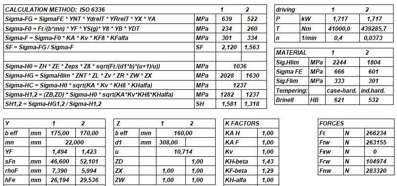
ZAR1+, ZAR4, ZAR5, ZAR7, ZAR8: Material Coefficient ZW according to ISO 6336-2:2019
The following material pairs are used according to ISO 6336-2:2006:
1. Surface-hardened pinion with through-hardened gear
2. Hardened pinion with hardened gear
Another material pair has been added in ISO 6336-2:2019:
3. Surface hardened pinion with ductile gear
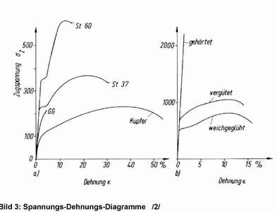
Ductility is the property of a material to permanently deform under load before fracture. In the picture on the left, St60, St37 and copper are ductile. But not GG (cast iron). In the right picture, tempered or annealed steels are ductile, but hardened ones are not. Surface-hardened steels have a soft core and therefore deform ductilely.
A surface-hardened or inductively hardened gear is now also rated as a ductile gear in ZAR. For a Brinell hardness greater than 314 HB, ZW = 1.0, which should be the normal case for surface-hardened gears.
For combinations other than those according to ISO 6336-2:2019, ZW = 1.0 is set.
Previously ZW was calculated for a case-hardened pinion with an inductively hardened gear according to case 1, which sometimes resulted in ZW < 1.
In the new version there is ZW1 for the pinion and ZW2 for the gear. The factor ZW calculated according to cases 2 and 3 applies only to the wheel (2) and not to the pinion (1), and in case 1 ZW1 (pinion) = 1 is set if less than 1 is calculated.
Also new in ZAR1+ is a warning if the selected material type and heat treatment do not match.
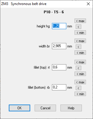
ZM3: Tolerances added to Printout
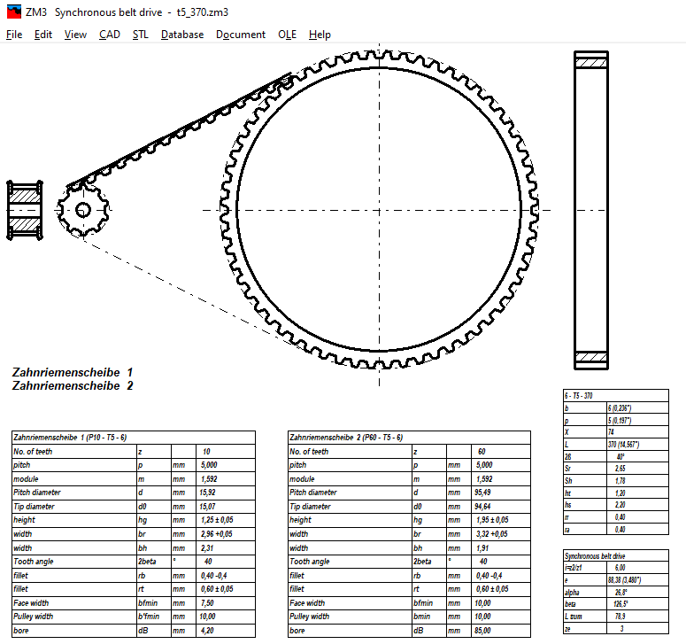
The dimensions hg, br, bh, rb, rt are now printed out with tolerances in quick views and printouts. Although the tolerances had already been calculated and taken into account when generating the profile (min/max), they were not displayed in the quick views until now.
