 | English
| Deutsch
Spring programs: energy-mass ratio as indicator for efficiency and lightweight construction
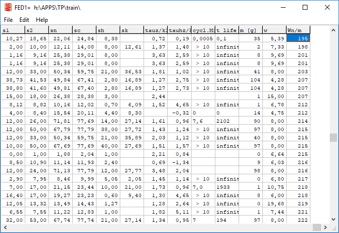
In the spring programs a new factor is introduced: energy-mass-ratio (W0n/m) as indicator, how much energy can be stored with 1 kg of spring material. This allows you to compare different spring types, materials and cross-sectional shapes. Therefore, "Wn/m" is also included in the table under "File-> Open Table".

The energy-mass ratio also decreases for increasing wire diameters because the tensile strength decreases. At first glance it is also astonishing to compare a spiral spring with a leaf spring made from the same piece of steel strip. The compared spiral spring could store 10 times more energy than the unrolled leaf spring. This is because the bending stress in the spiral spring is distributed over all coils, whereas with a clamped leaf spring the highest bending stress occurs at the bearing position. On the other hand, a torsion bar spring has almost identical values compared to a helical compression spring, because torque and shear stress is constant over the entire length.
The energy-mass ratio of rubber compression springs is surprisingly high. No wonder, because tensile pressure is distributed constant over the entire material volume. Metal springs are not practical in this form, cause spring travel is too small. But when using rubber springs as energy storage, hysteresis, relaxation and switching times should also be taken into account.
In contrast, helical springs are applied to torsion, and torsion springs and leaf springs on bending. The highest stress occurs only on the external fibres. In the neutral fibre in the middle there is no tension at all (waste of material). With hollow wire one could improve the material utilization.
Spring Programs: spring energy efficiency
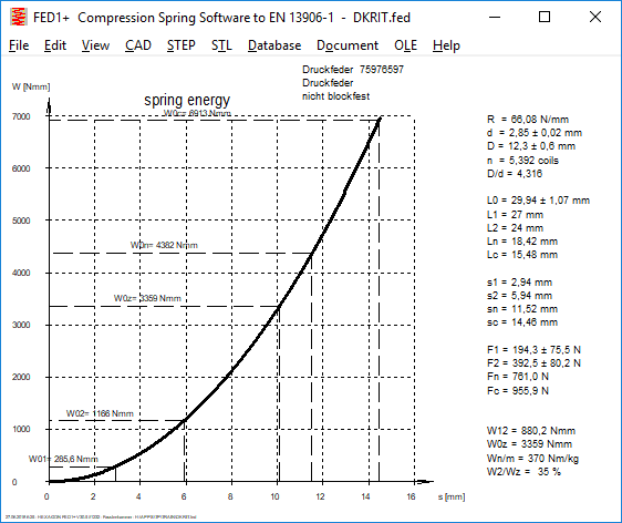
Another new degree of energy efficiency = W02/W0n or W02/W0z is used to indicate how much of the maximum usable energy of the spring will be used for the application. It should be noted that the degree of utilization can only be 100% for static applications, in case of dynamic application the (static) energy utilization factor must be less than 100%. For all springs except helical compression springs, disc springs and wave springs, the usable spring travel sn and the usable spring energy Wn are limited by the permissible shear stress or permissible bending stress. In contrast, helical compression springs are usually designed block safe so that the permissible shear stress cannot be reached at all, because the spring is previously on block. For this case, a theoretical spring energy W0z is calculated for helical compression springs, disc springs and wave springs, with theoretical maximum spring energy calculated from permissible shear stress or permissible bending stress.
       ----------------------------------------------------------------------
       spring energy between s1 and s2   W12      Nmm         186047
       ----------------------------------------------------------------------
       spring energy s2                  W02      Nmm         248063
       ----------------------------------------------------------------------
       spring energy sn                  W0n      Nmm         1699018
       ----------------------------------------------------------------------
       spring energy sc                  W0c      Nmm         2090832
       ----------------------------------------------------------------------
       spring energy tauz                W0z      Nmm         408125
       ----------------------------------------------------------------------
       spring energy min(sn,tauz)        Wn       Nmm         408125
       ----------------------------------------------------------------------
       energy efficiency                 W02/W0z               61 %
       ----------------------------------------------------------------------
       energy-mass ratio                 Wn/m     Nm/kg         257
       ----------------------------------------------------------------------
FED1+: Fn = F(tauz), W0z = f(tauz)
In the case of springs, the index n stands for usable length Ln, usable spring force Fn, usable stress taun = permissible stress tauz. In the case of compression springs, index n stands for the usable spring travel sn = Block Length sc safety distance Sa. If the spring is not block resistant and the permissible shear stress is already exceeded at spring travel sn, another usable spring force Fn ' at the spring travel sn ' appears in the F-s diagram. For this case, the spring energy W0z at spring travel sn ' has been added now, this means the usable spring energy until the permissible shear stress is reached.
FED2+ Quick Input
New Quick Input contains all input data integrated in only one large input window.
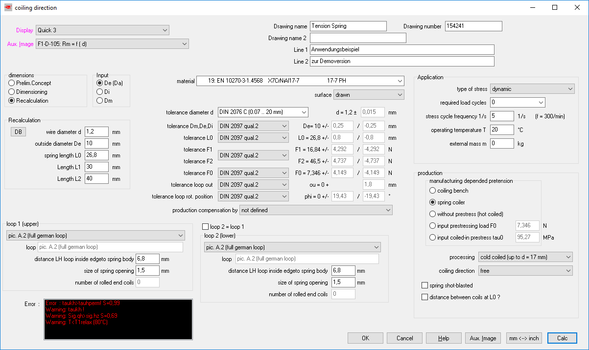
The old input windows (base data, text, material, production, tolerance, application, loops) remain available.
FED2+: Get default loop height
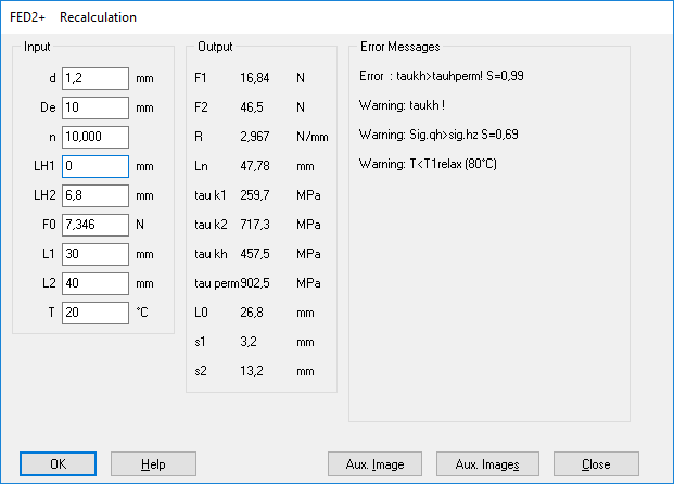
In FED2 + there are also several special methods for dimensioning and recalculation of tension springs (online input). Under "Edit\Dimension" and "Edit\Recalculation" a suitable loop height (depending on the selected loop) is now suggested when you input LH1=0 or LH2=0.
FED2 +: Torsional spring rate of extension springs
If the loops are twisted against each other, the tension spring is used like a torsion spring. For this case the torsional spring rate cm in Nmm/° is now calculated and printed.
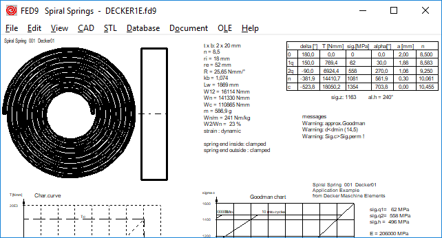
FED9: Usable spring travel of spiral springs
The usable spring travel is limited by the permissible bending stress. If the permissible bending stress is not exceeded even with full suspension on block, a safety distance Sa should be maintained, similar to the helical compression springs according to EN 13906. Since there is unfortunately no standard for spiral springs, in FED9 now similar to EN13906 "Sa = n * 0.1 * d" or "Amin = 0.1 * d" is set at static load. At dynamic load of warm-formed springs, Sa is doubled and with cold-coiled springs, Sa is 1.5-fold, analogous to EN 13906.
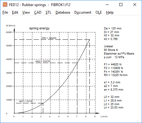
FED12: Spring Energy W = f (s)
New in FED12 for rubber springs is a diagram of the spring energy.
FED1+: Relaxation table
The relaxation table for working temperature and temperature limits in the Rx = f(t) diagrams had been removed for some time, because the temperature and material-dependent calculation of the shear module in accordance with the current EN standard made the calculation more difficult. The relaxation table is now displayed again.
WN4,5,6,7,8,9,12, WNXE, WNXK, LG2: Production drawing in standardized scale
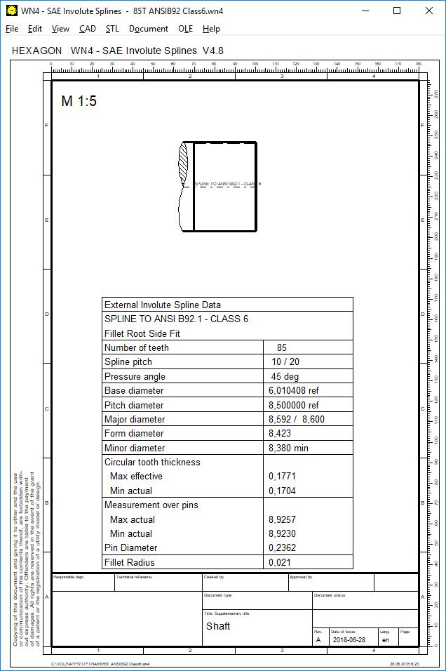
So far, a drawing of the calculated machine element has been fitted in an A4 sheet in maximum size. Now the drawing is inserted in the next smaller standard scale 1:1, 1:2, 1:5, 2:1, 5:1 etc.
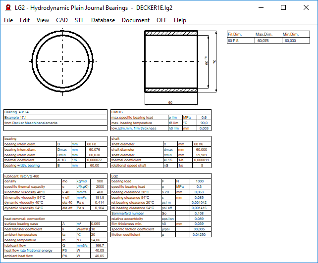
LG2: Quick3 View and Quick4 View
New in LG2 are Quick3 View and Quick4 View with drawing of the journal bearing and tables with dimensions and calculation results altogether on one screen (print with Ctrl-P or File\Print)
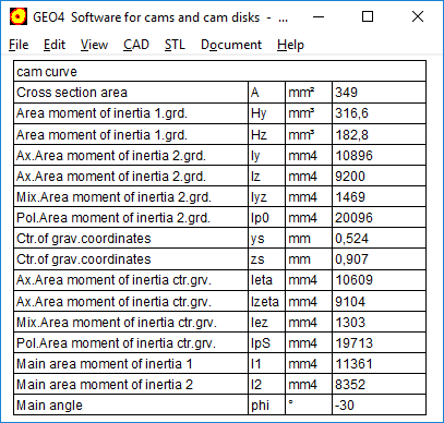
GEO4, ZAR4: Area, Area moment of inertia, center of gravity
For cams and noncircular gears, a table with area, area moments of inertia and coordinates of gravitation center has been added. Calculation and table are same as in GEO1.
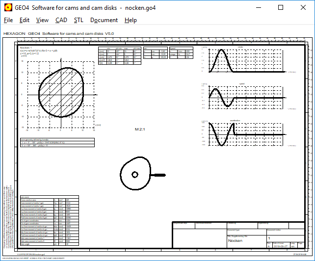
GEO4: Quick1, Quick3, Quick4 Views
New result screens Quick1, Quick3 and Quick4 with drawings, tables and diagrams of the calculated cams and cam shafts have been added to GEO4.
TOL2: Dialogue windows
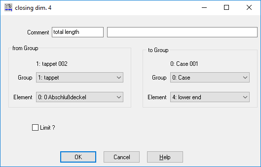
There were error messages in the dialog boxes for entering groups and closing dimensions, and the TL1 file name was not displayed. If you get any errors in TOL2, please send a screenshot with the faulty dialog box, then you will receive a free update.
SR1: Thread strip safety
If standard screws and standard nuts of the same strength class are used, the thread strip safety must not be proven, because according to VDI 2230 no thread can be stripped down in this case. But if you choose and calculate the nut material, you will be amazed to find that you receive a warning about thread strip safety. In search of the cause, in PRESSURE.DBF database we modified shear stress ratio of the nut strength classes "QUAL12" to "QUAL3" according to the equivalent VDI2230 values of the bolt strength class "taub/Rm" to 0.6 and 0.7 (so far the value was 0.577 for all). But that's not enough yet. Safety factor increases, but remains below 1. Then you can still reduce the thread tolerances, ideally at 4h/4h. If this is still not enough, you could only reduce the non-bearing thread length of the chamfers. But then you will get a new warning "mzu < 2P".
In the search for calculation examples, B2 from the VDI 2230 would be fine. A pity, under R11 stands only: "Omitted, since standardized nuts of a strength corresponding to the bolt are used."
SR1 calculates a minimum depth meffmin = 12 mm usíng thread tolerance 6h/6g, but the bearing length of the nut is only 14.8 2 * P = 10.8 mm. The thread strip safety is then 0.9. According to VDI 2230, the minimum depth is calculated with tolerances for the worst case. The thread strip safety at Rmmax means that in case of overload the bolt breaks and does not strip the thread. If the load entered is not exceeded, the thread strip safety applies to FMzul + FSA.
To represent the bandwidth of the minimum thread length of engagement meff at the highest and smallest tolerance, SR1 and SR1 + now also calculate the minimum length of engagement at the smallest thread tolerances and minimum tensile strength of the bolt. With example B2 from VDI 2230 You now get a bandwidth of 12.0 mm to 7.8 mm for the minimum depth meffmin, only by using min and max tolerance. This corresponds to a safety mtr/meffmin between 0.9 and 1.4.
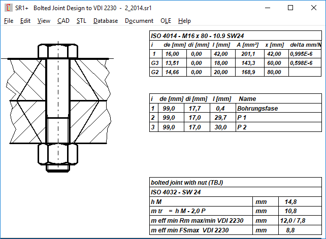
Thread strip calculation factors C1, C2 and C3 of VDI 2230 have been added to the printout of SR1+ for proof and recalculation purpose.
Configure Dialog window and dialog elements
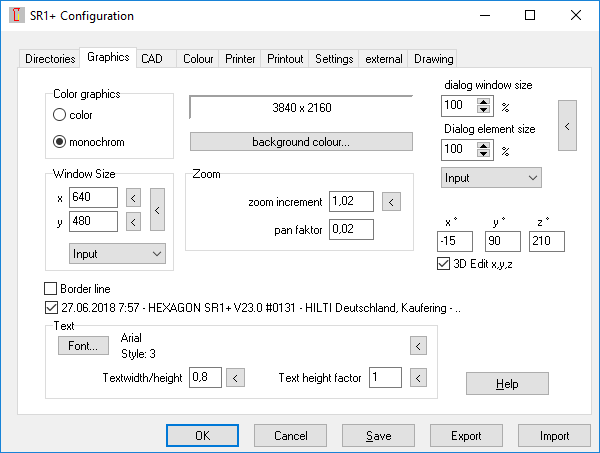
When large fonts or special dialog boxes are configured on Windows, the dialog boxes may be too large or too small. Then you have to configure "File\Settings\Graphics" "dialog window size" and appropriately "dialog element size". Default setting is 100% (first select "Input"). In previous versions you could drag the dialog box even bigger or smaller, but in newer versions there were mostly no scroll bars. So you had to configure the dialog window size correctly first. This change has now been reversed, so that even if the configuration is incorrect, you are not forced to cancel the calculation and to configure the dialog boxes first.
Comment about trade dispute and climate protection
Instead of responding to the US import duties on steel and aluminum with questionable "punitive tariffs" on whiskey, jeans, peanut butter and motorcycles, and thus to take off a customs avalanche, the EU should better appreciate import tariffs on steel and aluminium as an active contribution of the United States to global climate protection. Because it makes no sense to ship tons of steel and aluminum with high energy and pollutant emissions across land and across the oceans.
Also, the exit of Donald Trump from the climate change agreement is only honest: If I can't reach a goal, I'll admit that and leave it out. On the other hand, the other members of the climate change agreement are in breach of all climate protection goals, without any consequences. For the improvement of the carbon footprint of the exporting countries, the St-Al tariffs of the USA are helpful because the steel and aluminium production is extremely energy intensive.
And the level of US tariffs is not beyond the range: for bicycles from China, the European Union is raising a whopping 63.5% import duty (15% "normal" customs + 48.5% anti-dumping duty). That is why today in Europe you pay more money for a simple children's bike than for a four-stroke lawnmower with gasoline engine.