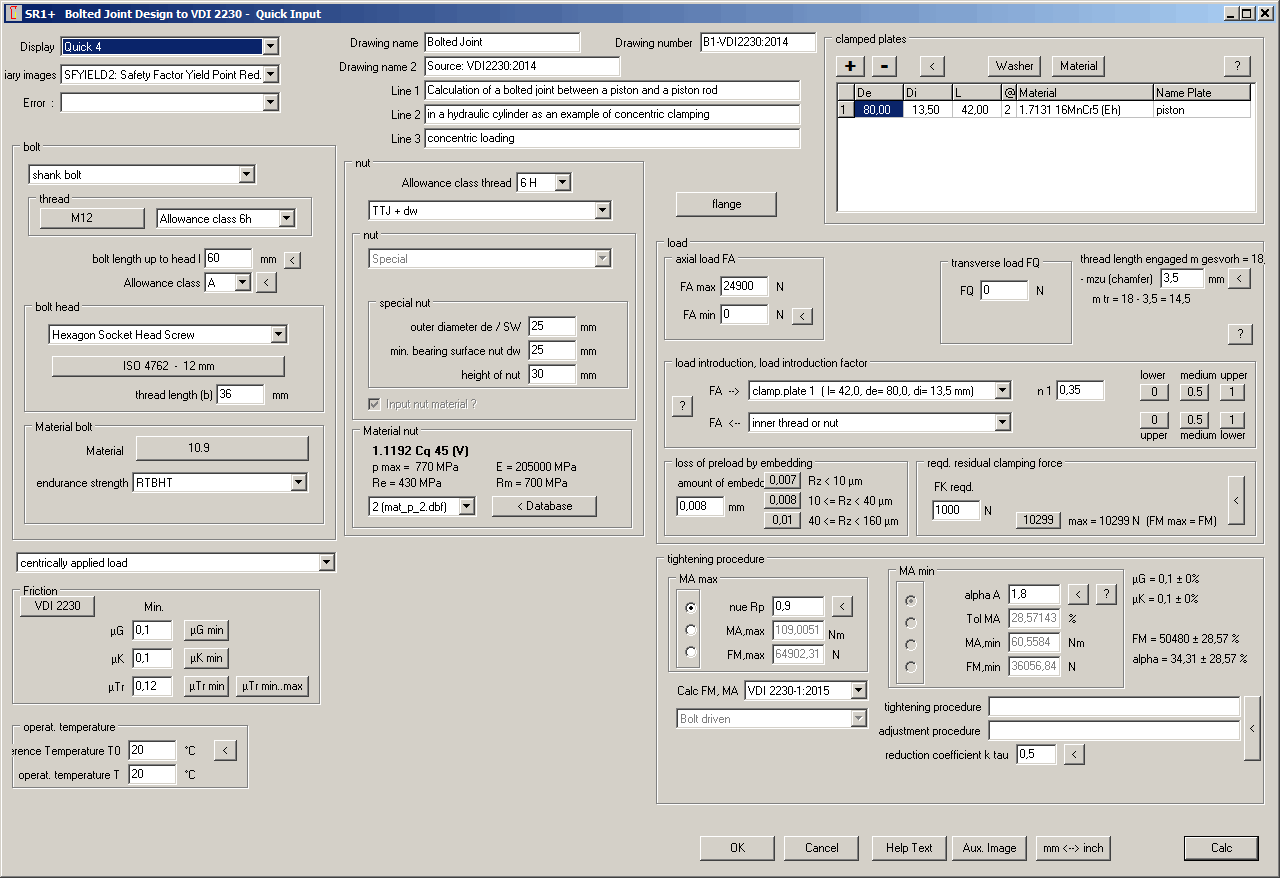

SR1+: Quick Input Window
New Quick Input Window of SR1 and SR1+ integrates all former input windows in only one dialogue window.

Quick Input Window provides a new option if you want to study the influence of one or more parameters in a specific diagram: select required diagram at "Display", then change input value and click "Calc" button to actualize the diagram. Until now, you could do so with the result graphic (Quick3) only.
If you configure help level 2, Quick Input opens automatic at program start.
The new Quick Input window in SR1+, due to large variety of input values, became relative large, 1280x900 pixel. If you want to display it together with the graphic result window on one screen, resolution should be 2560x1080 or higher. Minimum screen resolution required for SR1+ Quick Input is 1280x1024, but in this case result graphic window is covered completely by the Quick Input window.
You can skip Quick Input, well-known input windows of earlier versions are available furthermore.
SR1+: Compare FKR in Load-Extension Diagram
A customer asked why the residual clamping load FKR is not equal with the point of intersection in the load-extension diagram, as shown in VDI2230-1 figure 2. In fact, FKR is the intersection point for TBJ with bolt, but not for TTJ. And the reason is the "supplement for plate resilience δPzu" (equation 80,81,82). Thus, for TTJ the axial additional load FSA no longer calculated from the ratio of δP and δS only, but distorted by δPzu. Deviation is huge, using example 1 of VDI 2230, FKR is calculated 10.3kN, but the intersection poiunt in the diagram is only 2 kN. Deformation fPA is calculated with δP, not (δP+δPzu).
To get residual clamp load for TTJ from the intersection point of the diagram, you either must switch to TBJ, or at "Edit->Calculation method" "Elasticity" switch to "deformation sleeve (VDI2230-1986)". Then select "Load-Extension diagram->working condition min." to display residual clamp load FKR.


Image 1: B1 of VDI 2230-1: FKR does not intersect in FKR | Image 2: B1 as TBJ: FKR correct in intersection point
To get the required residual clamp load "FKerf" instead of "FKR", display "Load-Extension diagram->working condition reqrd.". Same situation here: intersection point is correct for TBJ, but not for TTJ.
It seems that equation (80) in VDI2230-1:2015 is wrong.
ΦK = δP / (δS + δP) is the deformation ratio of plate load ratio. If "δPzu" used in numerator to increase δP, it must also be used in denominator to increase δP.
According to VDI 2230-1:2015: δPzu = (w-1)*δM
According to VDI, w is the "joint coefficient for the type of bolted joint". w is predefined for two values only: w=2 for TTJ and w=1 for TBJ
To say it less complicated and more straightforward than VDI, without w:
δ
Pzu = δM for TTJδ
Pzu = 0 for TBJSR1+: Calculation Method δPzu
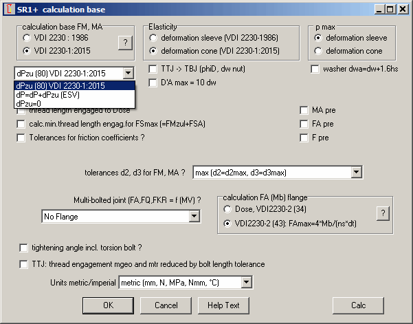
In SR1 and SR1+, you can now configure at "calculation method":
Use default method 1 if you think that calculation according to VDI2230-1:2015 is correct. Configure method 2 if elasticity of nut thread should be considered in δP. Configure method 3 if elasticity of nut thread should not be considered in δP.


If you configure method 2 or method 3, FKR is drawn correct in the intersection point of the load-extension diagram. With method 2 ("δP=δP+δPzu"), FKR=10.34kN (larger than 10.3 kN of VDI). With method 3 (δPzu=0), FKR=9.85kN (less than 10.3 kN of VDI).
ZAR4: Quick View
ZAR4 Software for noncircular spur gears got new Quick Views with drawing, diagrams and tables altogether on one screen.

For different screen size and resolutions different Quick View 1, 2, 3, 4 is provided. In Quick4 view, drawing, diagrams and tables are drawn together with an ISO 7200 drawing header. Quick View drawings can be loaded into CAD.

ZAR5: Pre-Dimension
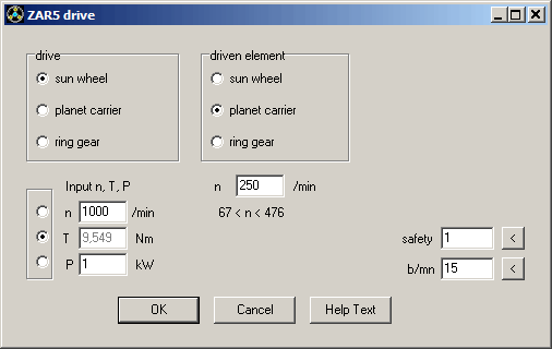
In Pre-Dimension of ZAR5 you have the choice to input two of the tree values speed, torque and power, and the third value is calculated.
And you can define a coefficient for safety and ratio face width / module. Safety less than 1 calculates smaller gears, and safety > 1 calculates larger planetary gears.
WN3: Shaft Stress
If you enter torque and additional bending moment in WN3, bending moment has no influence on pressure and safety pperm/pmax. According to DIN 6892, WN3 calculates bending stress Sigmabmax at the ground of the notch in the shaft from from bending moment.
WN3 now calculates reference stress of shear stress and bending stress
Sigmav = √ (Sigmabmax˛ + 3 * taumax˛), and shows an error message if yield point of shaft material is less than reference stress.
FED2+: Quick3 with Loop position angle
Loop position rot. angle with tolerance has been added to Quick 3 View.

New Software ZAR7 for Plus Planetary Gears

A plus planetary gear set is an epicyclic gear set with planet wheel pairs instead of single planet wheels. Stationary gear ratio is positive due to reversed sense of rotation. If planet carrier is blocked, sun gear and ring gear rotate in same direction.
For calculation of load-bearing capacity, contact ratio, specific sliding,.., meshing gear pairs have to be calculated separately. A plus planetary gear has 3 meshes: sun wheel with inner planet wheel, inner planet wheel with outer planet wheel, outer planet wheel with ring wheel.
ZAR7 calculates all gear pairs and meshes in one sequence.
Animation simulates rotating gear wheels and planet on screen.
Roller bearings for the planet wheels can be selected from included database, ZAR7 calculates bearing life expectation.
ZAR7 will be available soon.
New Software ZAR8 for Ravigneaux Planetary Gears
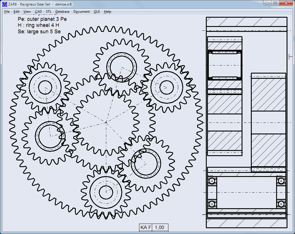
Ravigneaux gear sets are used in modern automatic and manual transmissions. Ravigneaux gear set is composed of two planetary gear sets: one plus planetary gear set and one simple (minus) planetary gear set. Plus and minus planetary set use a common ring gear and a common planet carrier. And the outer planet wheel of the plus planetary set is the planet wheel of the minus planetary gear set.
Ravigneaux gears have 4 ports (shafts, clutches): small sun, large sun, carrier, and ring gear. To be used as driving shaft, driven shaft, control shaft and idle shaft. If control shaft is blocked, 24 gears could be shifted in theory. Practically, Ravigneaux gears use 4 forward gears and one rear gear, and driven gear is always the ring gear.
For calculation of load-bearing capacity, contact ratio, specific sliding, .., meshing gear pairs have to be calculated separately. A Ravigneaux planetary gear has 4 meshes: small sun wheel with inner planet wheel, inner planet wheel with outer planet wheel, outer planet wheel with ring wheel, large sun wheel with outer planet.
ZAR8 calculates all gear pairs and meshes in one sequence.
Roller bearings for the planet wheels can be selected from included database, ZAR8 calculates bearing life expectation.
ZAR8 will be available soon.
New Software GR1 Gear Toolkit
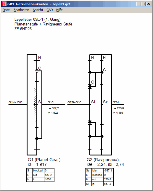
GR1 calculates speed and transmission ratio of multistage gears composed of gear pairs, planetary gear sets, plus planetary gear sets, Ravigneaux planetary gear sets or Simpson planetary gear sets.
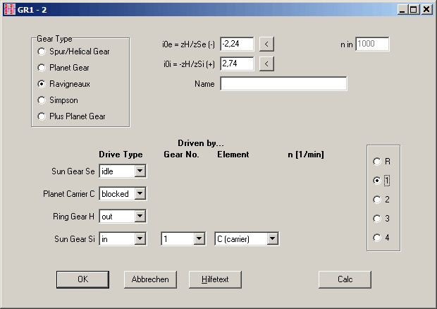
GR1 will be available soon.
Making network versions running faster
Main reason if network versions run slowly is too much network traffic: too much data sent to and requested from file server. At "File->Settings->Directories" you can configure important settings and thus make network versions faster:
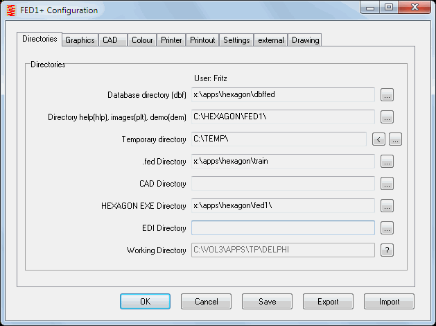
Most important setting: Temporary directory must be a local drive! Best choice is to configure a RAM disk.
New Option "Copy DBF -> TEMP"
Another optimization is to copy the dbf database files into a local directory and configure this local drive as database directory. But in this case an actualization problem remains: you must regularly synchronize database files, or copy from network into local drive. Therefore a new option is available now: if "copy DBF -> TEMP" is checked, dbf files are copied at program start from R/O network directory into temporary directory, and used from temp directory during the session. Using this new option, you do not have to copy dbf files nor change configurations: database directory remains the write-protected network database directory.
If you, furthermore, copy the help files (hlp, plt, dem) into a local directory and configure this local directory (Directory help, images, demo) , you have only one network access at program start and the network version runs as fast as a locally installed individual license.
Printer Portrait-Landscape
When changing printer at "File->Printer", sometimes the printing orientation changed into the standard setting of the new printer. This was changed now, printing orientation portrait or landscape remains unchanged when selecting another printer.