
New Software FED16 for Constant Force Springs
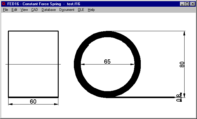
FED16 calculates constant force springs made from spring strip coiled on a mandrel. Constant force springs must not be clamped, constant force at reel up results from the fact that the spring endeavours to return to its original roller shape.
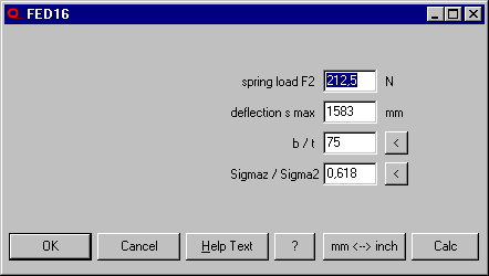
In pre-dimension of FED16, you can input force and maximum deflection, and FED16 calculates the spring dimensions.
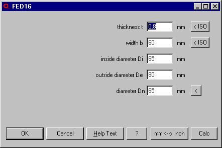
In recalculation of FED16, you enter spring dimensions, and FED16 calculates force, max. deflection, bending stress and life expectation.
FED16 is available now, price of individual license is 225 EUR.
FED1+: Quick Input
New Quick Input of FED1+ integrates most input fields of Edit menu and result screens of View menu altogether in one dialogue window. This eases spring calculation, especially for beginners.
Only special calculations such as individual input of material properties, dimensioning material, dimensioning installation space, recalculation load-deflection line, or load spectrum has to be chosen from Edit menu. A high-resolution display is helpful when using new Quick input, then you can place dialogue window and graphic window side by side.
Result screens with drawings, diagrams and tables as well as auxiliary images can be selected under "Display" and "Aux.age". If you configure help level 2, Quick input dialogue window is opened directly after program start.
FED1+, 5, 6, 7: Warning P/Di > 0.7
If coil pitch P is larger than 70% of inner coil diameter Di, this can complicate or forbid spring production. In this case a new warning appears. If dimensions cannot be changed, ask your spring manufacturer if spring can be produced without problem.
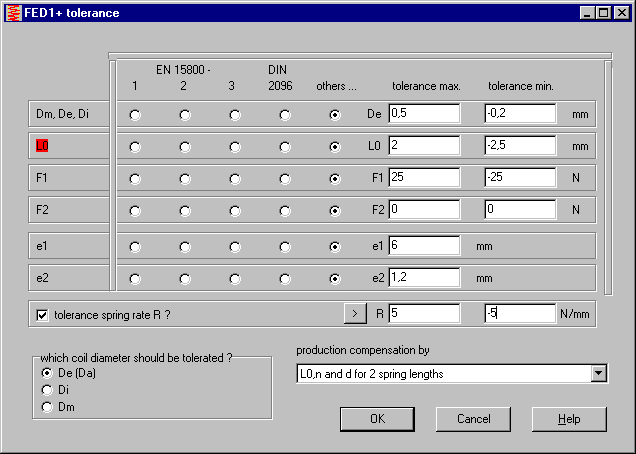
FED1+: Spring rate tolerance
Alternative tolerance for the spring rate R has been added in FED1+. You can input upper and lower tolerance of R, if required. If tolerances of spring loads F1 or F2 should be suppressed in this case, set it to 0.
FED2+, FED3+: Input spring rate at Dimensioning and Pre-Dimensioning
Same as in FED1+, alternative input of spring rate has been added in extension spring software FED2+ and torsion spring software FED3+. At "Edit->Calculation method" you can configure if input of R should recalculate F1 or F2 or sh (T1 or T2 or alphah in FED3+).
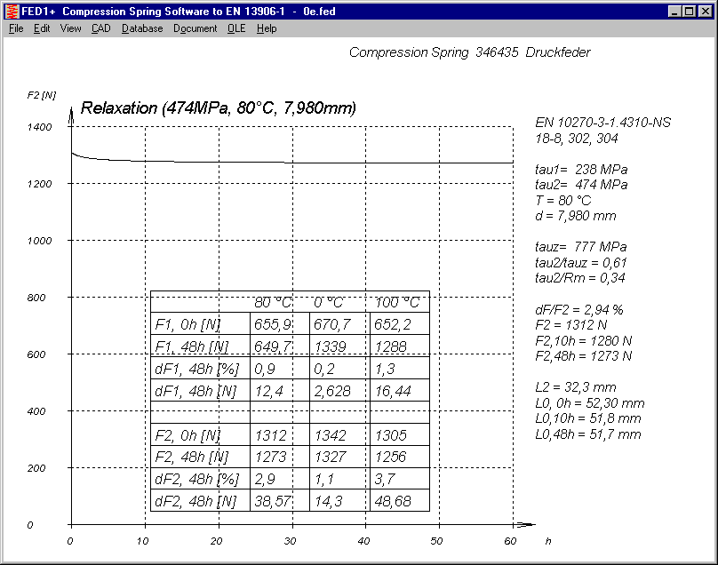
FED1+,2+, 5, 6, 7: Table in relaxation-time diagram
Tables in relaxation-time diagrams Rx%=f(t) and RxF2=f(t) were printed with differing values compared with printout. Table with relaxation for operating temperature and min and max temperature (input at Edit->production drawing) was corrected and relaxation data for spring length L1 have been added. In Quick4 view of FED1+ and FED2+, relaxation diagram RxF2=f(t) has been added.
FED2+: Consider bending radius of loops
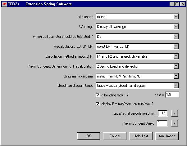
Until now, stress correction factor q for tension in the loop was calculated from loop radius Di/2. Now you can additionally consider the bending radius of the loop by input of ratio bending radius / wire diameter to calculate the stress correction factor q for bending stress. The higher q value will be considered. Loop stress can become higher as calculated until now, if ratio of bending radius to wire diameter is less than 2.
SR1 calculation option washer dwa=dw+1.6hs
If this option is set, SR1 calculates bearing area of the washer to next clamping plate according to VDI 2230 as dwa=dw+1.6hs. Until now, it was not considered that external diameter of the washer can be less than dwa, if external diameter of washer is relative small and thickness of the washer is relative large. In this case, surface pressure was calculated too low. Now, dwa was limited to external diameter of the washer.
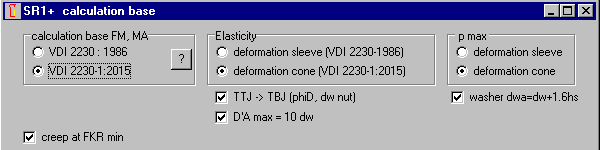
SR1 calculation option elasticity: deformation sleeve (VDI 2230-1986)
After implementing calculation of elasticity with deformation cones instead of deformation sleeves, it has been found now that since then the old calculation with deformation sleeves, if configured, required two computing procedures to get the result. Bug was fixed now.
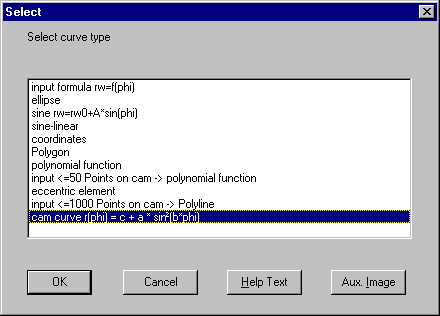
GEO4 Input Cam Curve
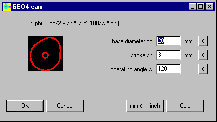
Parameters stroke, operating angle and base diameter of the classic cam curve r (phi) = c + a * sinē (b*phi) can now be entered directly instead of typing the formula. This saves time at input as well as at calculation and animation.
To optimize the generated cam geometry you can export and re-import cam curve as DXF. Or optimize in CAD and then import polyline in GEO4.
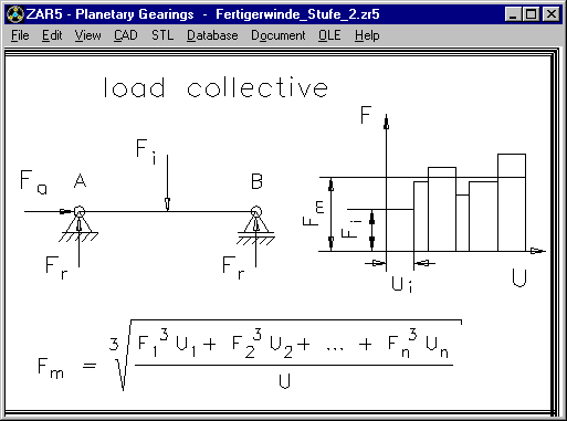
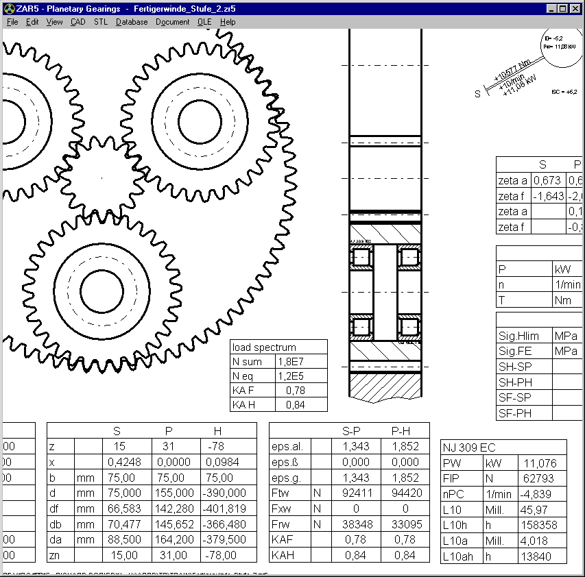
ZAR5: bearing life if load spectrum
Bearing life of the planetary roller bearings was calculated from nominal load. Now, ZAR5 calculates average bearing load if a load spectrum was defined:
Fm = ((F1ģ * U1 + F2ģ * U2 + .. +Fnģ * Un) / U) ^1/3
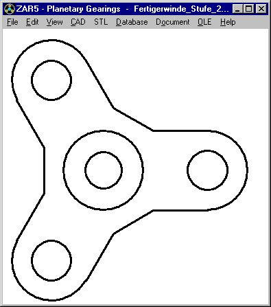
ZAR5 Planet carrier with coupling shaft
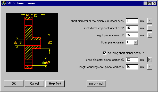
At "STL->Carrier" and "CAD->Carrier", planet carrier with coupling shaft can be generated and printed. CAD and STL files can be used for creating planet gear models with 3D printer, or as draft for CAD planet carrier drawing.
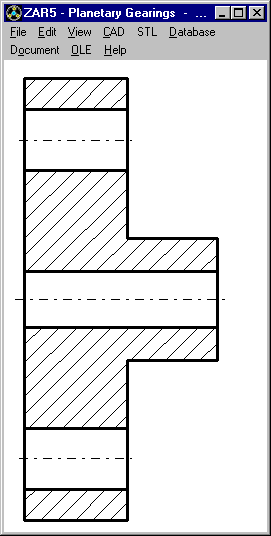
ZAR5 Taper roller bearings and cylinder roller bearing NJ in X and O configuration
Taper roller bearings in O configuration are now drawn aligned with the carrier plane. And if two cylinder roller bearings of type NJ are selected, you can choose X and O configuration for the drawing.
WN2+ Buttons e2min and e2max interchanged
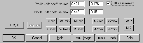
At "Edit->Dimensions Tooth" you can input (WN2+ only) tooth dimensions with gap width e2min and e2max of the internal spline and tooth thickness s1min and s1max of the external spline. Unfortunately, buttons e2min and e2max were interchanged and had to be exchanged now. e2max belongs to M2min and e2min belongs to M2max.
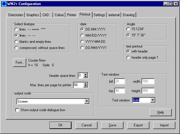
Automatic text window size
Same as graphic window size and dialogue window, size of text window for printout can be set to "automatic".
IGES problem with large file name
IGES header contains the file name. If this is too long, header wrote over border, thus IGES file caused error. Now the file name in the IGES header is shortened to 30 characters.
Problem with standard network printer
A customer had problems with printer configuration. Instead of the printer dialog box he got an error message "There is no default printer currently selected".
We found now that this problem can occur if the default printer is a network printer that was externally configured. In this case you must install the default printer once again from your workstation and use local printer drivers if possible. Or simply define a local printer or pdf printer as default printer.
STL files for 3D printer
Most STL files generated by our calculation programs are surface shells, not closed volumes. External surface is drawn in mathematical positive direction and empty space in negative direction. Not every 3D printer software can handle this type of STL file. We recommend Cura software of Ultimaker (download free).
VDFI Spring seminar
Association of German spring manufacturers VDFI arranges a spring calculation seminar on October 20 in Aalen, hold by Prof. Dr.-Ing. Tillmann Körner of HEXAGON Ingenieurbüro.