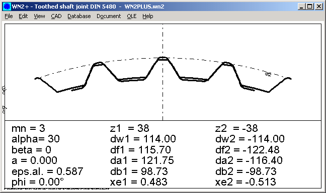
WN2+ for Non-Standard Involute Splines

WN2 calculates involute splines joints according to DIN 5480. Definitions of DIN 5480 (profile shift x calculated from nominal diameter dB, constant tooth height factors) cannot be modified. Now, we offer an extended version WN2+ with additional input of profile shift x and tooth height coefficients ha/m, hf/m, and tooth root diameter rhof/m. Nominal diameter dB is calculated from profile shift x1 for this case.
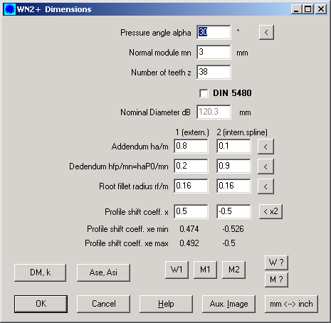
Additionally, you can enter span width or over-pin-dimension to get profile shift of an existing gear in WN2+. This allows you to design the partner profile for an existing external or internal involute spline.
Price of WN2+ is 380 Euro. Upgrade WN2 to WN2+ is 161 Euro in 2006 (later 192,50 Euro).
FED3+ Spring Drawing
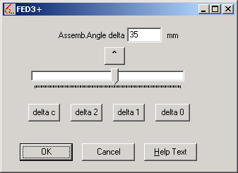
At View menu, you can enter leg angle (delta) for 2D and 3D drawing of the spring. Default drawing is unloaded spring (spring angle delta0).
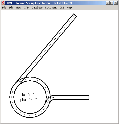
FED3+ Tip: Use Tangential Legs
Stress correction coefficient q in FED3 (similar than k in FED1) considers stress concentration in wire surface dependent from coil ration Dm/d. But for bended legs, stress in bending radius r may be higher than in coil surface. For this case, the term (2 * r / d + 1) instead of w = (Dm / d) is used to calculate peak stress of the torsion spring. To increase efficiency of torsion spring, define large bending radius, or better use tangential legs.
FED7 – Maximum Shear Stress
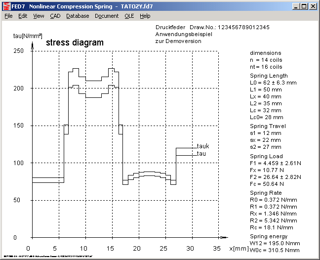
At View->Stress you can display stress distribution along spring body for any spring length. Maximum value for L1 and L2 is used as tau1 and tau2 now.
FED5 – Calculate Block Length with d or dmax
According to EN 13906 standard, block length Lc is calculated with maximum wire diameter (Lc = (nt+..) * dmax, with dmax = d + max. tolerance d. Now, you can configure to calculate block length with d or dmax at "Edit->Calculation Method".
FED5 – Quick-View
Shear stress at block length tauc has been added at Quick-View, and spring rate at block length Rc was removed.
FED6 – Generate Symmetric Spring Segments (Mirroring)
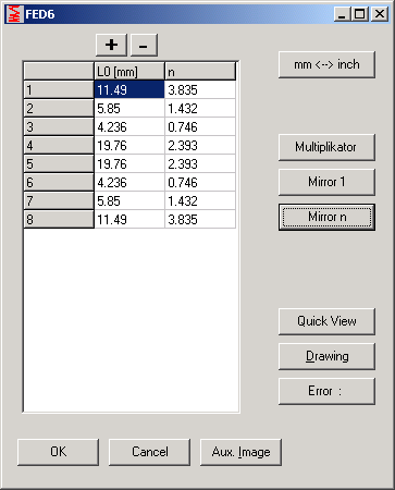
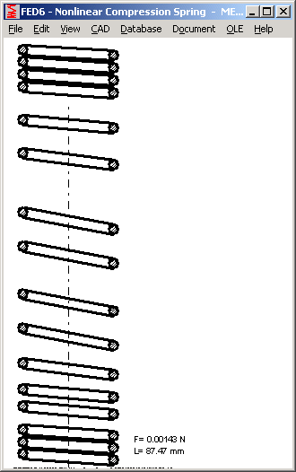
When calculating springs from progressive load-path diagram, you get a spring with high-pitch segments on one side and low-pitch segments on the other side of the spring. Now, a function has been added to a generate symmetrical spring body. At "Edit->Spring Sections->Table" you can mirror all sections against the first or the last segment. Number of sections is doubled, all section lengths and nos of coils are halved. The characteristic line of spring stays the same, because sequence of sections does not matter.
FED9 – Coil Distance a1, a2
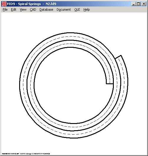
Because external radius Re is reduced by spiral spring travel, also coil distance a is reduced by this influence. Until now, coil distance was calculated from higher number of coils n with constant Re. Now, reduced external radius Re1 and Re2 is considered for calculation of a1 and a2. Re1, Re2 and Rec have been added to printout. On block position, alpha c = 0 and Rec = Ri + nc * t.
External Radius: Rex = Lw / (pi * nx) - Ri (x = 1, 2, c)
Coil distance: ax = (Rex - Ri) / nx - t
FED9 – Spring Drawing
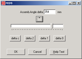
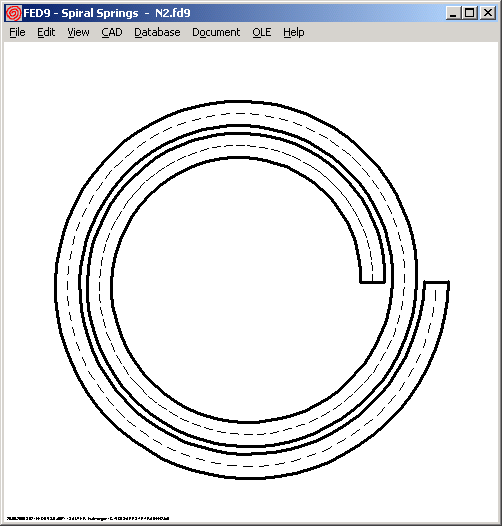
Since version 3.0, you can generate a drawing of the spiral spring for any spring angle between delta0 and deltac. In earlier versions, spiral spring was always drawn with delta0.
WL1+, LG1 : Life Expectation for Angular Contact Ball Bearings
Lifetime exponent 10/3 (for cylindrical rollers) instead of 3 (for balls) is now used for calculation of angular ball contact bearings.
GEO1+, TR1 – Profile Database
Profile database is now initially indexed by size (instead by name).
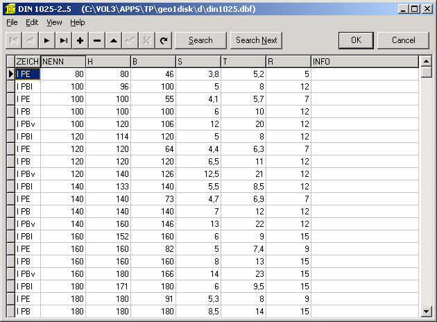
If you want to sort by another item, use right mouse key to click into caption field (this is a common option in database window of all programs).
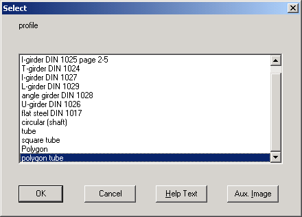
GEO1+, TR1 – Profile Round ,Tube, Square, Polygon
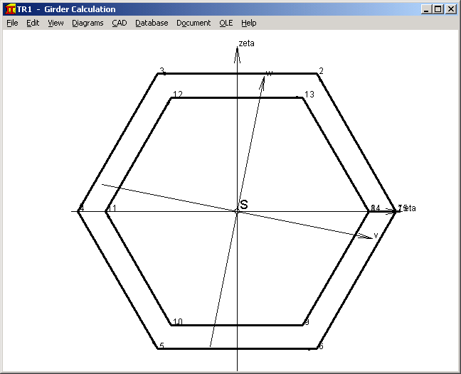
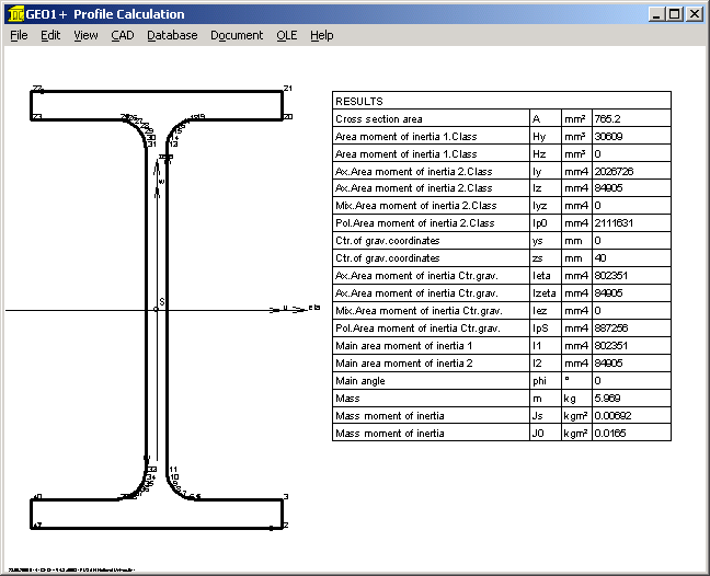
Coordinates for round, tube, square, polygon and polygon tube profiles are generated by the program now. This saves time for inputting coordinates.
GEO4 – Stroke for Bucket Tappets and Roller Tappets
Input of tappet dimensions was only used for drawing generation until now. Diagrams for speed and velocity were based on cam radius r = f (phi). New version 2.0 of GEO4 considers tappet of flat form (bucket tappet) or circular form (roller tappet) in calculation and animation. Path diagram for cam radius r = f (phi) was replaced by stroke s = f (phi). Velocity and acceleration diagram are derived from stroke curve.
TR1 – Natural Frequency
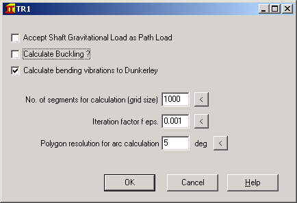
TR1 calculates natural frequency of the girder, if option "Calculate Bending Vibrations to Dunkerley" was checked.
ZAR1 - CAD Gear Profile
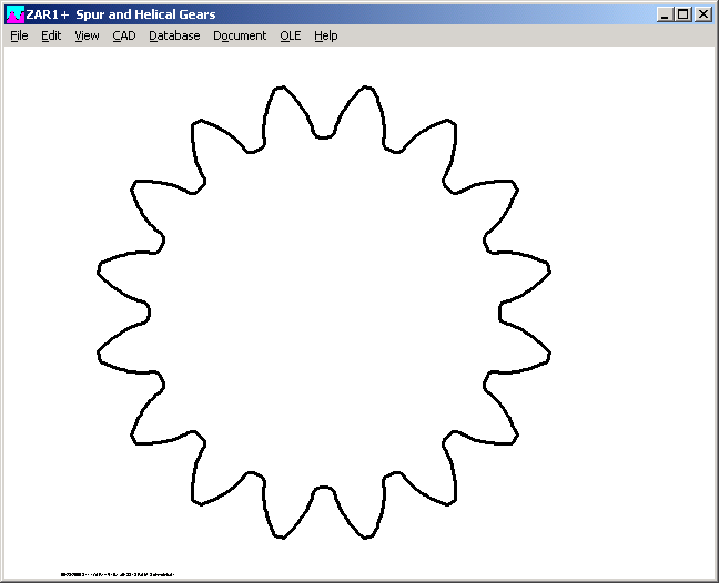
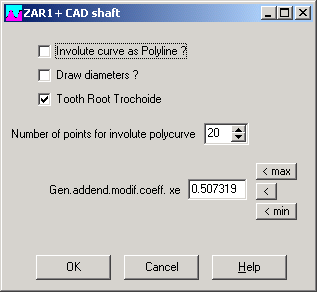
Menu selection for mostly used CAD drawing of gear profile was simplified and reduced to two mouse clicks. At "CAD->Tooth Shape", you may modify profile shift and drawing parameters, then generate CAD drawing.
ZAR5 – Bedding of Pinion Shaft to DIN 3990 Part 1
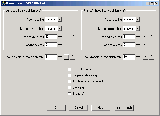
Additional input for calculation to DIN 3990 part 1-3 (vs. Part 41) has been integrated into one window. Mouse click into "<" buttons suggests: tooth contact bearing = image a, bearing type = image a, bedding distance lS = 3 * b, lP = 1,6 * b, offset s=0 for planetary gearings.