
English Deutsch
FED9 – Spiral Spring Software

The new FED9 Software was made for calculation of spiral springs of flat steel. In Pre-Dimensioning, you can calculate a spiral spring by input of torque and stroke angle. At Dimensioning, FED9 calculates a spiral spring from Torque1,2, stroke angle, interior and exterior coil diameter. In Recalculation, you enter the dimensions of an existing spiral spring, and FED9 calculates characteristic line and torque for any spring angle. Characteristic line of spring, Quick output, and Goodman diagram may be plotted to screen or printer..

WST1 – material size
The values for tensile strength and yield point in WST1 refer to a material thickness/diameter of 10..16 mm. Tensile strength and yield point for other diameters of ferritic steel can be calculated by this formula:
Rm = Rm10 * [1.2 – 0.2 * log (d)]
Rm10 = tensile strength at d=10mm
d = diameter in mm
Tensile strength and yield point as function of the material diameter can be displayed as diagram with the newest version of WST1.

Yield point:
Re = Re10 * [1.2 – 0.2 * log (d)]
Re10 = Yield point at d=10mm

Thanks to G.F. Dose for his help and verifying the formulas.
FED1+ Production drawing
Max. characters for surface protection was increased form 30 to 45, and for additional remarks from 60 to 100. Material name 3 was added at the material field. The tolerances e1 and e2 are not on the drawing, if defined 0. (or if spring ends are not ground). Thanks to Marco Vignaroli of Benelli Armi, Italy, for the improvement suggestions.
FED1+ Spring ends
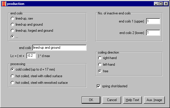
Formulas from DIN 2089 for calculation of the block length:
Lc = (nt + x ) * dmax
x = 1.5 for cold-coiled springs, spring ends lined-up
x = 0 for ground end coils.
x = 1.1 for hot-coiled springs, end coils lined up
x = -0.3 for hot-coiled springs, end coils lined up, forged and ground
If grinding more or less, you can select ".." and enter the appropriate block length coefficient.
Thanks to Mr. Künzli form Baumann Springs in Rüti, Switzerland, for his suggestion.
FED3+ Calculation Method
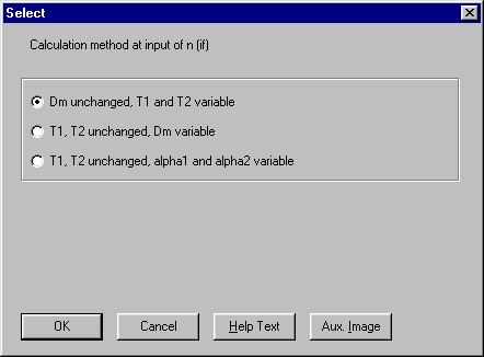
At Dimensioning, spring torques T1 and T2 changed, if you modified number of coils. With the newest version of FED3+, you can configure, if coil diameter or spring angles should be changed instead. Thanks to Mr. Göbel, ABB Heidelberg, for his suggestion.
FED3+ Edit Tolerance
At tolerance input, the deviations for quality 1,2,3 are dispülayed online. The tolerance for coil diameter was not correct at this input window, now it is ok. Thanks to Mr. Füssmann, Iserlohn.
FED2+ Edit Tolerance
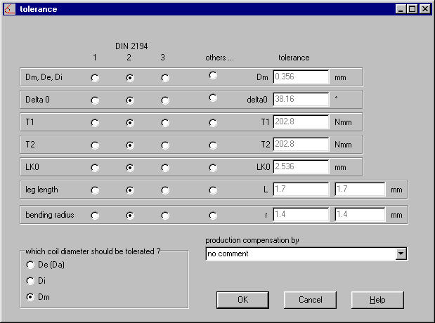
At tolerance input, the deviations for quality 1,2,3 are displayed online. The tolerance for the loop position was not correct at this input window, now it is ok. Thanks to Mr. Wilke, Brenne Springs, Iserlohn.
ZAR1+ Tooth drawing of ring gears
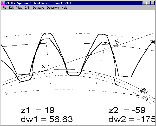
The tooth root radius of ring gears is displayed with the new version of ZAR1+. Thanks to Mr. Lamprecht of Zahnradwerk Pritzwalk for his suggestion.
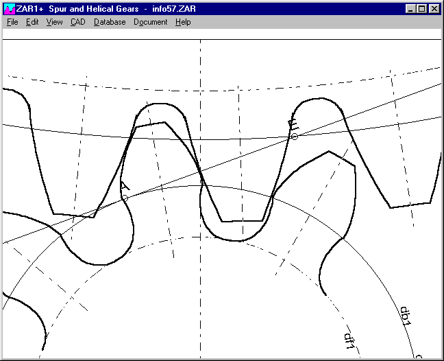
ZAR1+ Tooth Curve with Undercut
The trochoid curve of the tooth root at undercut could be displayed only by the tooth shapes of the tool with the previous versions. Now it can also be displayed as polyline. Although, it works not with any tooth shape. So the new option can be switched on and off at "View-Polyline Tooth root".
TOL1 – Form Feed
You can now configure a form feed at the printout between element list and closing dimensions.
Thanks to Mr. Bähr of Siemens, Bad Neustadt, for his suggestion.
TOL1 – Long description of closing dimensions
Long descriptions are printed only if the fields are not blank.
DBFEDIT V2.0 - HTML-Export
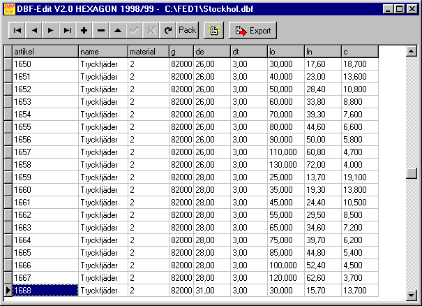
DBFEDIT can print the records of dbf files up to 6 fields, or export to txt or HTML files.
Our customers can download DBFEDIT as freeware tool from
www.hexagon.de/history/tools.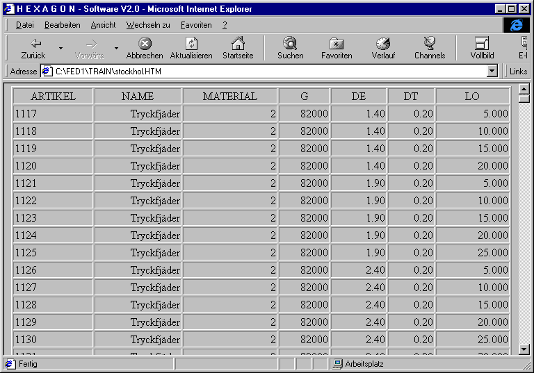
SR1 - Print Macro
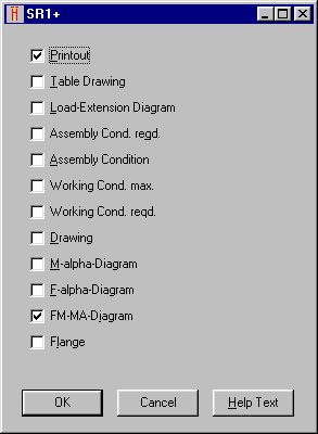
All the marked items are printed one by one. Print macro setting is saved with the SR1 file. If you always want to have the same predefined settings, save it in a "NULL.SR1" file.
SR1 – Help Index
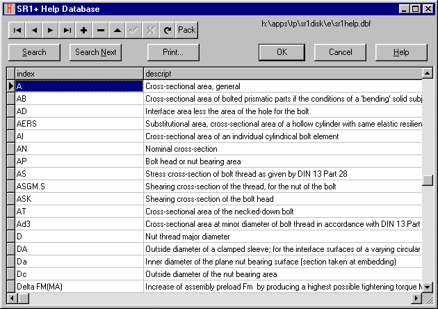
At "Help-Index" you can display a description of the signs used in SR1 and VDI 2230. The database may be extended by the user. Thanks to Ralph Shoberg for his suggestion.
HPGL-Manager – Conversion Pen Width to Color
You can configure HPGLMAN to convert the command PW (Pen Width) instead of SP (Select Pen) to a layer, colour or tool in DXF, IGES, Postscript or NC code. Newer ink and laser printers use PW instead of the pen plotters SP.
Configure text window size
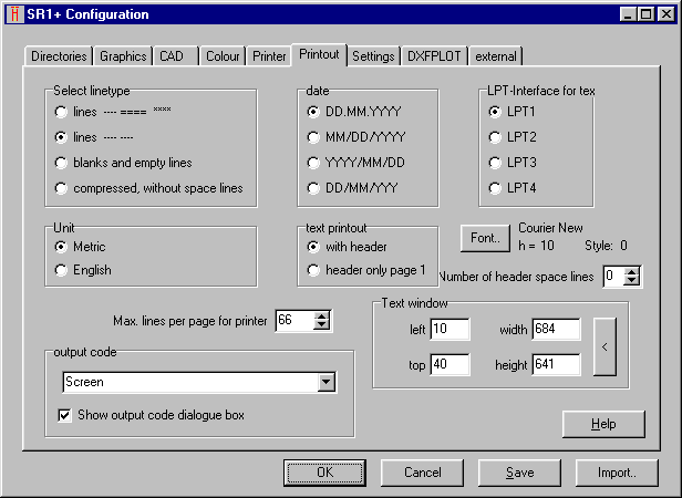
With the newest releases, you change the window size by mouse, then goto "File-Settings-Printout", and save the configuration.
Printout Database
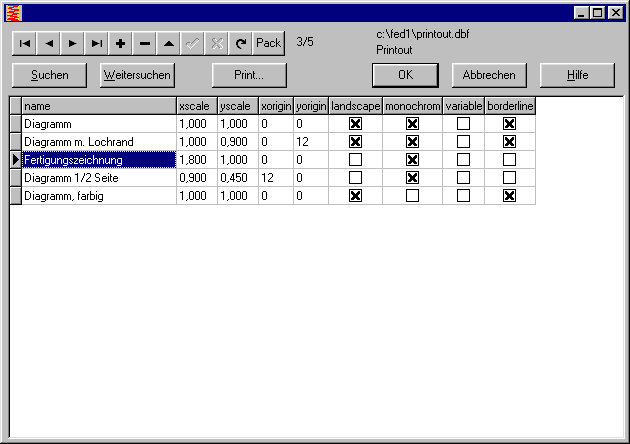
The cursor jumps to the previous position, when calling the database again. (in older version, it always jumped to the first position).
Configuration - Import
The cfg files of all HEXAGON-Programs have the same structure.
For example, you can import the the FED1+ setup to WL1+, then modify the Directory-settings only.