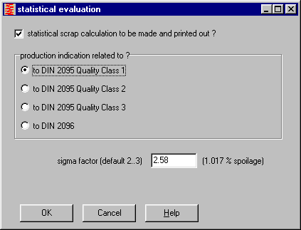
FED1+ Statistical Evaluation

Provided that the tolerance middle is aimed for during manufacture, scattering and spoilage can be calculated for the target values from the bell curve of normal distribution. The pre-set values determine to which quality grade can be manufactured (1, 2 or 3). This value is dependent upon the machines used and the manufacturing method. This must be clarified with the manufacturer.
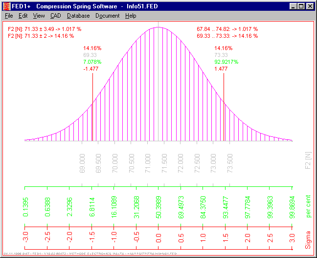
The example shows that quality grade 1 can be manufactured with approximately 1% spoilage. With a spring force of F2=71.33N this results in a deviation of +/- 3.49N for this spring. This means that 99% of all springs lie between 67,84 and 74,82N. However, a spring with F2=71.33 +/- 2N is required. This tolerance can only be manufactured with a spoilage of 14%. 100% checking/sorting increases the spring price extremely, and the spoiled springs must still be paid for.
FED2/FED2+ NT Version
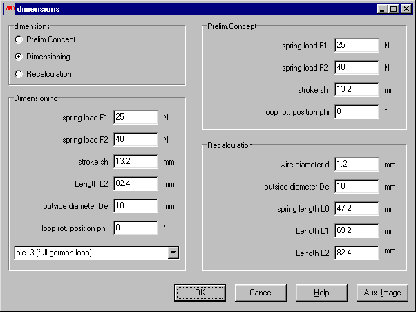
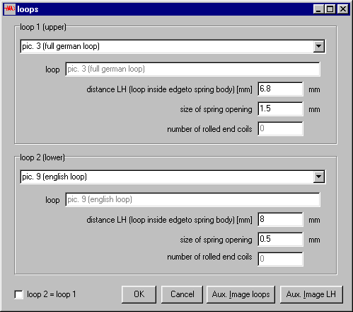
The new 32-bit version input for extension spring calculation has been simplified. Under "File->New" or "Edit->Quick" you can now choose between Preliminary Concept, Dimensioning or Recalculation. When hook eyes or curled threaded bolts are selected, FED2 will calculate the spring with optimum utilisation counter-balanced via the eye height LH. For other eye shapes, the value LH can only be altered very marginally. The counter-balance is then achieved via the wire or thread diameter.
When "Recalculation" is selected, you can enter any eye or eye height for both spring ends.
FED3+ Natural Frequency
The natural frequency for a torsion bar can be determined by a calculation using the mass moment of inertia of the spring body and the movable part of the spring. As the spring end of the movable spring is the only part to carry out the complete movement, only one third of the mass moment of inertia of the spring is taken into account.
FED5 Increasing/decreasing Pitch
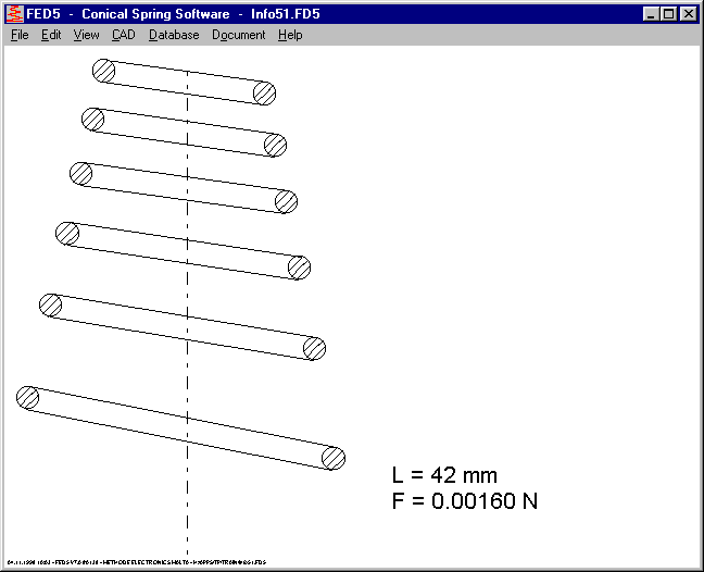
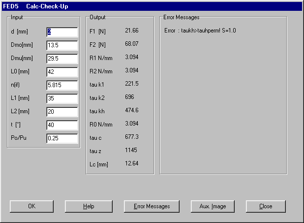
New in FED5 is the calculation for conical compression springs where the gradient increase or decrease is linear. The gradient ratio Po/Pu (gradient, first coil / gradient of last coil) alters the progression of the spring characteristic curve. The linear range of the spring characteristic curve can be extended when the coil distance at the greatest coil diameter is greater than the smallest coil diameter. In the reverse the progression starts earlier when the gradient of the greatest coil diameter is smaller than the smallest. Until now these have been greater deviations when the spring force F2 has not been in the range of the spring characteristic curve. In the new version the gradient ration has been altered so that F2 is within the linear range, this reduces the deviation of the entered forces. The gradient ratio Po/Pu can be re-entered in recalculation (gradient of the highest coil/gradient of lowest coil).
Animation - Single Step
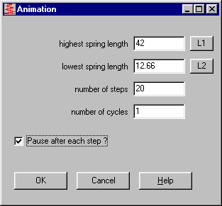
The 32-bit version allows you to set single step mode. This means the next drawing doesn’t appear until you have pressed the ‘+’ button with the mouse. The spring programs now display the spring length and spring force. This now allows the calculated values to be compared step by step with the measured spring characteristic curve.
FED8 - Polar Moment of Inertia
The polar moment of inertia (lp) for torsion bars was too small by a factor of two. I would like to thank Mr Rabe of GEZE for bring this to my attention.
SR1 - Compression Load
In the event that a bolt joint is only loaded by pressure, or when for alternating load the spring rate for the clamping piece is smaller than the bolt, the residual clamping load Fau must be checked. This has now been included in the program.
The minimum residual clamping loaded is calculated as follows:
FKRmin = FM/alphaA - FZ + FSA - FA
For tension load, this value is in relation to the seams which are load-relieved by tensile load. At the bolt head or nut the clamping force is greater by FA. For compression load the relieved seams (exactly the reverse) are at the bolt head or nut. The minimum clamping force is therefore:
FK = FM/alphA - FZ + FSA
with FSA<0. In SR1 the values FSAu and FKumin are newly output, for FKumin<FKerf a new error message appears.
I would like to thank Mr Gallaun of Siemens SGP, Graz, Austria for the help on this.
WN1 – 32-bit Version
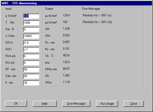
The user interface of the WN1 32-bit version has been greatly simplified.
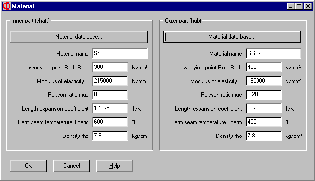
You can now enter material data for the shaft and nub in one window, or select them from the data base.
By simply moving the mouse during online input you can now have a description of the abbreviations used displayed in the input and output windows.
TOLPASS - Save File
In 32bit version of TOLPASS you can now save the calculated fittings in a file with the ending .TLP.
Window Size for High-resolution Graphics
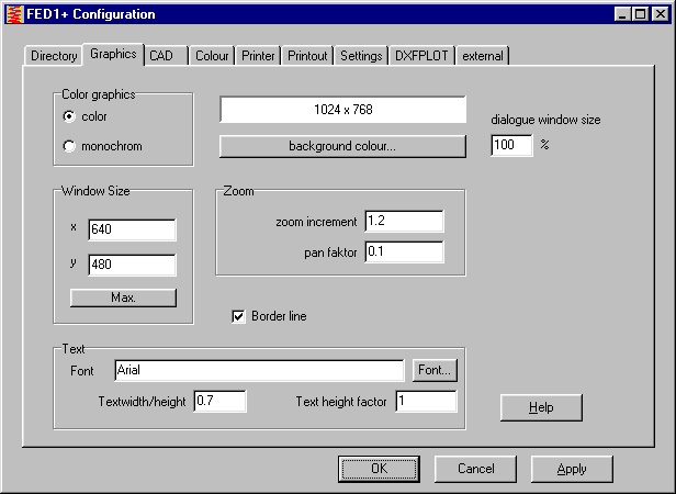
When you are working with a high screen resolution (1024 x 768 or higher) and have configured large fonts these won’t fit in the input window. This can be compensated for by altering the window size from 100% to 130% under "File->Settings->Graphic". For bringing this to my attention I would like to thank Mr Neumann-Henneberg of Method Electronics in Mriehel, Malta.
NT Version Printout
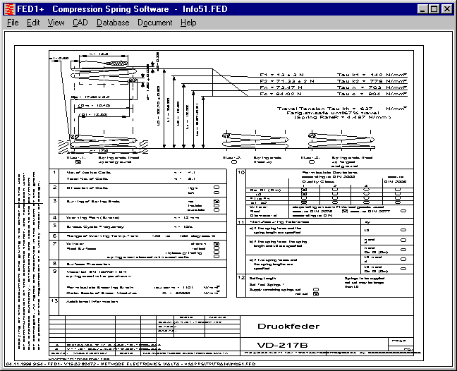
When printing out a diagram with the 32-bit version, the screen is adjusted to the page size. The crossways printouts are very good, with the exception of diagrams in which only half of the screen is filled out. When printing out lengthways, the diagram will be very narrow. Use this trick to obtain a scaled printout: double click with the left mouse button on the drawing surface, the drawing will then be adjusted to match the screen limits. Although the drawing appears ‘stretched’ on the screen, the proportions will be correct when printed out lengthways. Even better printouts can be obtained by using our plot program DXFPLOT.
ZAR1+ Online Geometry
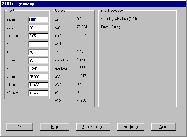
With online input of geometry the accuracy of the addendum modification coefficient and axial distance is increased. The axial distance is always displayed with three decimal places. Until now a>100mm was rounded off to two decimal places. This may mean that the addendum modification coefficient and axial distance can differ at the third decimal place from standard input to online input.
ZAR1+ Flank Direction
ZAR1+ now requires input of the flank direction for gear 1. For gear 2, ring gear the same direction is given, and for gear 2, spur gear with outer toothing the opposite direction is given. The axial distance is given with an accuracy of 0.001mm. I would like to thank Mr Schön of Grob-Werke in Mindelheim, Germany for pointing this out.
ZAR1+ DNf
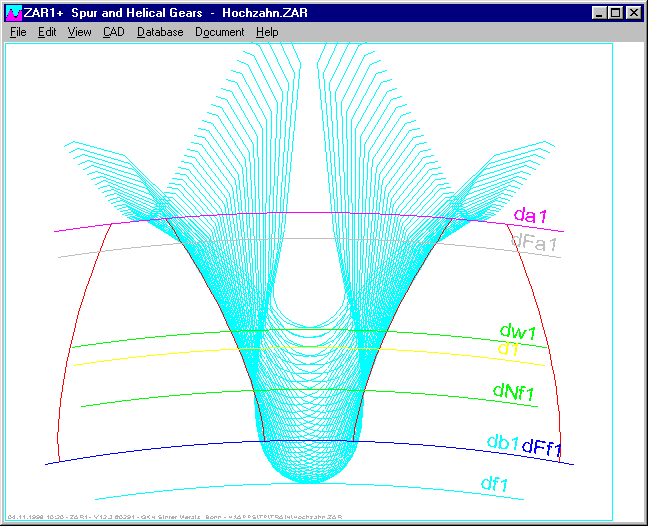
In the tooth and gear drawing the Fußnutzkreisdurchmesser dNf is included in the drawing. This simplifies the evaluation for deciding when toothing tool to use.
ZAR1+ Tolerance for Machining Allowance
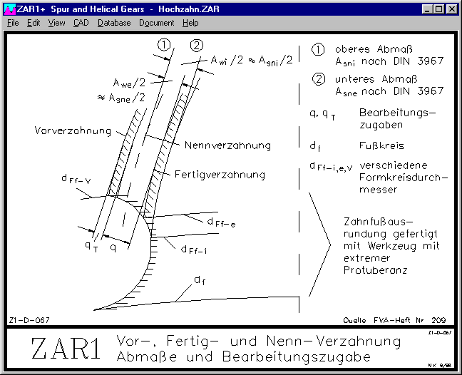
The tolerance for a machining allowance can now only be positive (previously + and -). q is then the minimum machining allowance which cannot be changed by tolerances for pre-machining. q should be greater than the tooth thickness tolerance Tsn, otherwise in the most extreme case, the greatest mass for the manufacturing preparation will already be reached. For q > Tsn an error message will be displayed.
ZAR1+ Extended Table
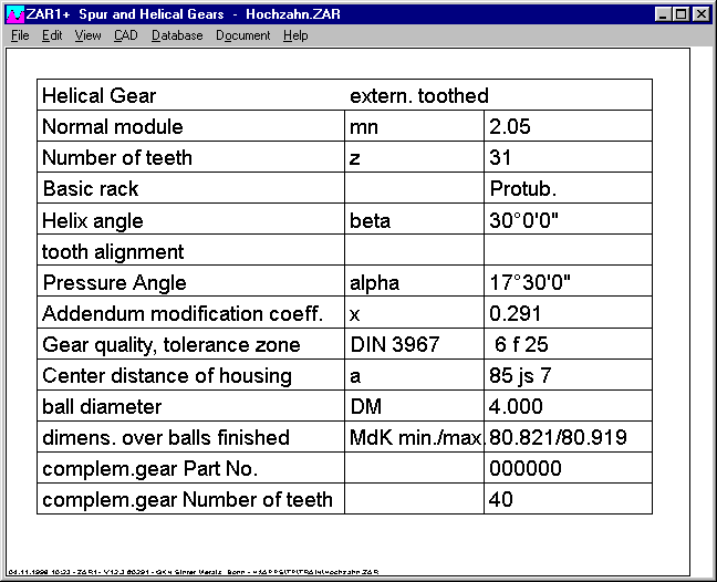
The table with toothing geometry the value ‘test measurements’ has been added. You can now choose between tooth width, mass over balls and mass over pins. For this improvement suggestion I would like to thank Mr Lamprecht of Zahnradwerk, Pritzwalk, Germany.
ZAR1+ Gear Rack - Checking Measurement
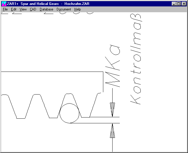
Gear racks can be calculated with ZAR1+ by entering z2=2000 for the number of teeth (or -2000 for a hollow gear). For tooth numbers >1000 a checking measurement is given out for the distance between the ball or roller diameter for the tooth tip line.
WL1+ Chain dimensioning
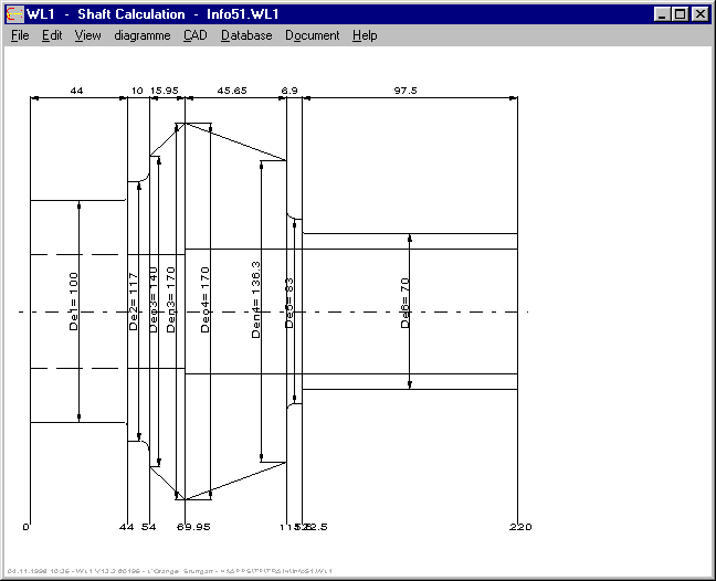
For the shaft dimension system you can choose between co-ordinate dimensioning, chain dimensioning, or both.For this suggestion I would like to thank Mr Hilmar Müller of Konstruktionsbüro Müller in Wollbach, Germany.
WL1+ Export Diagram
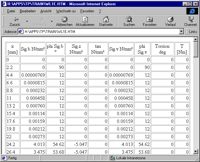
From bending and reference stress you can now export the resulting appropriate angle. Diagram: Export as HTML file. For this idea I would like to thank Mr Listner of Daimler-Benz.
HPGL Manager – Scaled Plots
Plots, which had been scaled with Scxmin, xmax, ymin and ymax were displayed reversed if the command wasn’t finished with ;. This can occur with plots done with the Windows NT driver HPGL/2.