Englisch
Deutsch
Info Letter No. 49 - June 1998
Copyright by HEXAGON Software 1998
ZAR3 - Drawing Document
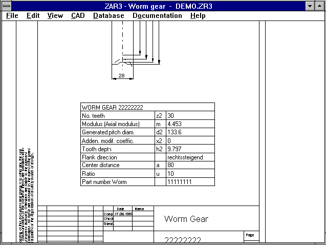 With the new version, you can generate a DIN A4 drawing with all
the most important dimensions as a DXF or IGES file which can then be
imported into CAD. Or you can use DXFPLOT to print the drawing out
directly on a plotter or laser printer. In the new ZAR3
"Document" menu, you make entries about the manufacturer, date,
changes and so on, these will then automatically be used by the
program for the drawing header.
Calculations document replaces drawing
Manufacturing drawings such as those in ZAR3 can now be generated by
most HEXAGON mechanical engineering programs. We recommend that you
only archive the calculation file instead of the CAD drawing. All
necessary drawing information is included in the file. When changes
are made, the machine element is re-calculated, the results are
checked, the changes are added to the index and a new manufacturing
drawing is printed out. As there are no CAD drawings, you can
prevent the worst-case scenerio of drawings being changed, without
the machine part being re-calculated with the new data.
WL1+, TR1 Material Data Base
As an alternative to the WL1WST.DBF material data base, the material
for shafts, or supports can now be taken from the WST1 data base file
WST1BASE.DBF. There are over 500 data records (steel and NE metals)
to choose from.
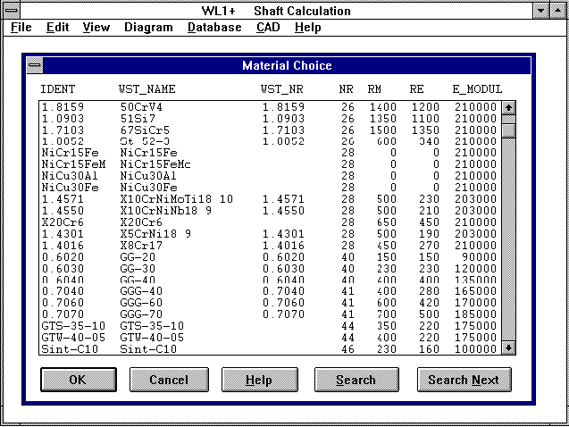 When using the WST1 data base, please note that the sensitivity
value eta k is not included in the data base. This must be entered
by the user. The data base files WST1BASE.DBF and WST1DYN.DBF are
included in the programs WL1+ and TR1.
ZAR1+ Gear Rack Calculation
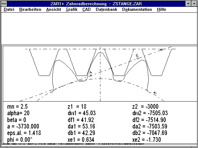 A pinion/gear rack pair is calculated by entering gear 2 as a gear
with a very high number of teeth (2000 or -2000 for a ring gear).
However, please remember that the allowance for tooth play is very
large for the calculation of the selected tolerance field due to the
relation with the generated pitch diameter. For this reason, the
values asne and Asni for gear 2 should be entered manually. There is
an auxiliary picture for the calculation of gear racks - ZSTANGE. If
this is not included in the list, please go to "New" or "Insert" and
select zstange.plt. A sample calculation (zstange.zar) can be
downloaded from the internet under
"http://www.hexagon.de/history/support"
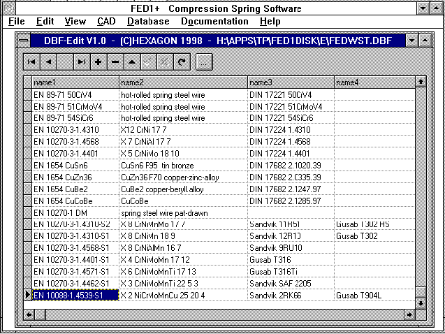
New Spring Materials
A new material from the Sandvik company has been added to the data
base FEDWST.DBF. The file can be downloaded from the internet under
"www.hexagon.de/history/files"
(For user and password see info letter).
Spring Materials - Data Base
The input for the spring materials has been simplified. You can now
enter two characteristic points for the tensile strengths and Goodman
diagrams in relation to the wire diameter. The program uses these to
calculate the parameters for the equations.
Rm = RM0 - DRM * log(d/DR0)
tau zul = Rm * 0.56 (for compression springs)

Parameters for the Goodman diagram:
tauo = TO1 - log(d/DT0) * DTO1
tauu = TU1 - log(d/DT0) * DTU1
Gradient of the lines = DTG
When extending the data base, the fields for the Goodman diagram can
be left empty, which results in there being no fatigue stress diagram
for this material. The fields G, E, RMO, DRM and RMMAX however, must
be completed, otherwise the new material cannot be used.
If you have a table or a diagram with the tensile strength in
relation to the wire diameter, you can use this to calculate the
parameters Rm0 and DRM. The reference wire diameter DO can usually
be defined as 1mm for cold-formed wire.
Example: The following is known about a material, that the tensile
strength for a diameter of 1mm = 1850 N/mm▓, and Rm for 10mm = 1140
N/mm▓. For 2mm Rm = , 1640 N/mm▓.
Calculation:
The values for d=1mm and d=10mm are entered, the program then
calculates:
Rm   = RM0 - DRM * log(d/DR0)
1850 = RM0 - DRM * log(1mm/1mm)
1140 = RM0 - DRM * log(10mm/1mm)
The logarithm of 1 is 0, the first equation results in RMO=1850
N/mm▓. The second equation then has the following result after
adjustment:
DRM = (RM0 - 1140)/log(10/1) = 710 N/mm▓
resulting in:
Rm = 1850 - 710 * log(d)
used for d=2 results in:
Rm = 1850 - 710 * log(2) = 1636 N/mm▓,
The deviation from the table value amounts to 4 N/mm▓.
HPGLVIEW for Windows NT
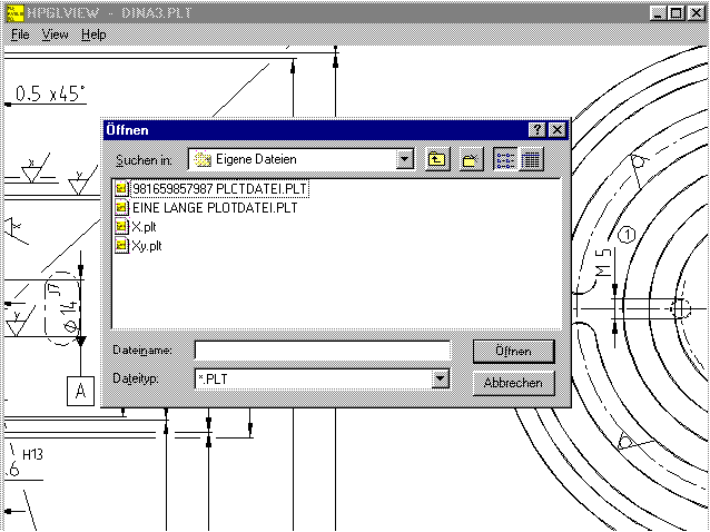 There is a new 32-bit version of HPGLVIEW, this now supports long
file names. This version runs under Windows 95, Windows 98 and
Windows NT 3.5, 4.0 and 5.0. However it does not run under Windows
3.1. Compared to the 16-bit version, the user interface and dialogue
windows have been improved. The new HPGLVIEW version can plot files
in the HP-GL format or the HP-GL/2 format with up to 250,000 drawing
elements being displayed. In the 16-bit version the number of
drawing elements displayed has been increased from 100,000 to
250,000. If this is not enough for you, you can use the HPGL
Manager. The Manager can go up to 500,000 drawing elements for the
16-bit version. The number of drawing elements for the 32-bit
version is only limited by the size of your PCs RAM. You require
64MB for a drawing of around 1 million lines. Registered users can
obtain an update for the newest 32-bit version. The 16-bit Windows
version is still available, it can be installed under Windows NT too,
but only supports file names with the usual 8.3 convention.
Decimal Sign: Comma instead of Point
In all programs you can now set whether you wish to use a decimal
point or comma under Settings. This is especially important for
export of tables and printouts to Excel, Quattro Pro etc. Depending
on language version or settings, you can now use a point or comma as
the decimal sign.
Calculation Proof with Reference Calculation
The program disks for machine element calculation programs contain a
file called "TRAIN". This file includes calculation samples from
taken from different literature, e.g.
- DIN Norms
- VDI Guide Lines
- Niemann: Machine Elements
- Decker: Machine Elements
- Roloff-Matek: Machine Elements
- Haberhauer-Bodenstein: Machine Elements
- K÷hler/R÷gnitz: Machine Parts
- Hinz: Verbindungselemente
- Schorcht: Metal Springs
- Holzmann: Festigkeitslehre
- Zammert: Working Design Calculation
- Knaebel: Schwingungslehre
- Dubbel: Mechanical Engineering Handbook
You can use the calculation samples to check the calculation steps
and to check the programs.
SR1 - Tolerance Class
For the thread deviation of screws and nut threads, different
tolerance classes are determined in DIN 13. The most common for the
outer thread are 4h, 6h, 4g, 6g, 4e and 6e. For nuts 6H and 6G are
the most common. As with ISO fits (TOLPASS, TOL1 and WN1) or with
tooth clearance (ZAR1), H means less clearance (pairing H-h in the
most extreme case is clearance free), g(G) and e stand for large
clearance. Tolerance class 6 stands for normal tolerance, this class
requires a smaller tolerance during manufacture. In SR1 the core
diameter d3 and the flank diameter d2 have until now been calculated
according to the tolerance class 4h or 6h. The greatest dimension is
the same for all h classes. With the new SR1 version, you can as an
alternative, enter the values for d2 and d3 manually. This effects
the strength calculation (core cross-section) and tightening torque
(due to surface friction and radial friction). For the information
about the tolerance tables I would like to thank Mr Uhde and Mr Mohr
of KAMAX in Osterode, Germany.
SR1 - Nut Material
 When screw and nut are combined from the same strength class, the
screw-in depth need not be calculated. It is in any case safe
against stripping. For special screws, or when a nut of lower
strength is used with a screw of higher strength, the stripping
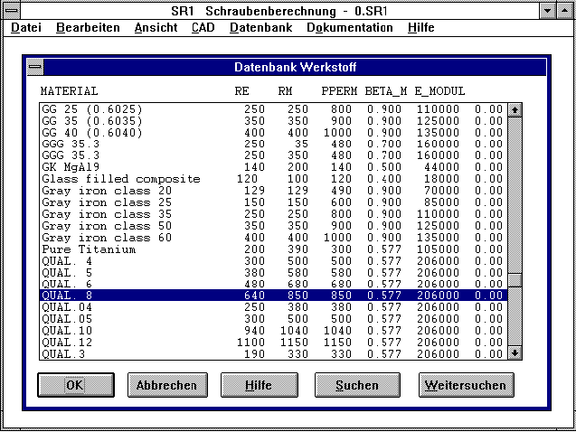
safety must be calculated. The nut material can be selected from the
data base "PRESSUNG.DBF", which can also be used for clamping pieces.
Thank you to Mr Dose for this improvement suggestion.
FED7- Special-Compression Springs and Serial Mounting
There is now a light version of the FED7 software for calculation of
compression springs of any shape available for 785DM. FED7 can
calculate compression springs with changing coil distances, coil
diameter and wire diameter by defining cylindrical spring sections.
You can equally well calculate the characteristic curve and the path
for spring ratio, spring operation and natural frequency for
compression springs serially mounted having different wire and coil
diameters. In comparison to the full version, the light version does
not have the interfaces for DXF, IGES and DXFPLOT. Spring animation
is not possible, the feature for automatic generation of the spring
section for barrel-shaped, waisted and conical compression springs is
not available.
FED2 - sideways upended eyes
A quarter of a turn less is required for sideways upended eyes. The
eye position for eyes sideways upended on both sides is 180° instead
of 0° for an even coil number. This was not previously taken into
account. For this suggestion I would like to thank Mr Jöckle of
Bernina in Steckborn, Switzerland.
WN1 - Torque
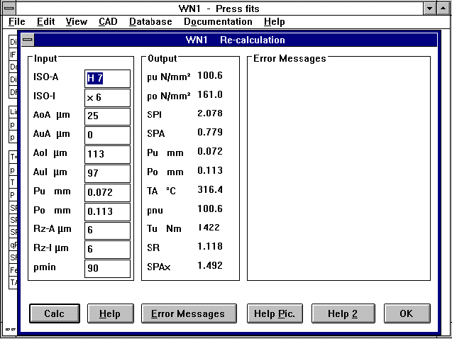 Upper and lower values for the transferable torque under the
prerequisite that no transferable axial force occurs are now newly
calculated and displayed (under standard printout, quick-output and
output field in re-calculation). The measurements for the shaft and
hub drawings are provided without decimal places. For this
suggestion I would like to thank Dr. Wege of the Highschool for
Technology and Economics in Leipzig, Germany.
SAM 4.0 by Artas
There is a new version (4.0) of the SAM Gear Analysis Program
available. HEXAGON has exclusive rights to sell this program in
Germany. The most important new features are:
- DXF import/export
- Zoom, lines, color settings
- Improved operation movemet definition
- Transformation features
The update for the new version costs 20% of the licence fee and can
be obtained from HEXAGON or directly from Artas. Please state when
you order whether you require the 16 or 32-bit Windows versions.
Further information and a demo version are available on the internet
under "www.artas.nl".
HPGLMAN/DXFMAN - ARC, CIRCLE
Some programs use an arc with start point equal to end point
or 0° to 360°, instead of a circle in the HPGL format. These methods
are also used to convert in HPGL-Manager, CNC code, postscript, DXF
and IGES, etc. Some programs only draw a point at 0° when loading
and arc from 0° to 360° from a DXF file. For this reason this
drawing element in the new programs is automatically converted to a
circle (CIRCLE command) when converting to DXF. For this information
and test files I would like to thank Mr Hartkorn of PSB, Pirmasens in
Germany.
French Versions
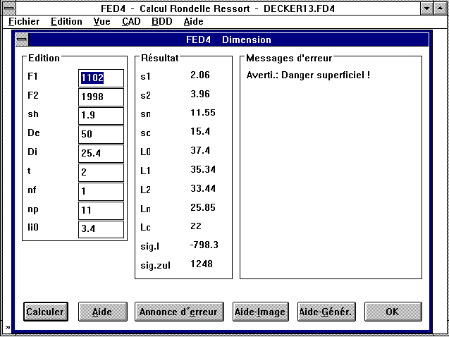 Our cup spring program FED4 and our HPGL Manager, DXF Manager and
HPGLVIEW are now available in French. The translation of the
technical terms has been improved in all French versions of the
spring programs. I would like to thank Mr Ghysel of Ressorts
del'Oise, Therdonne, and Stephanie Stojanovic, Paris.
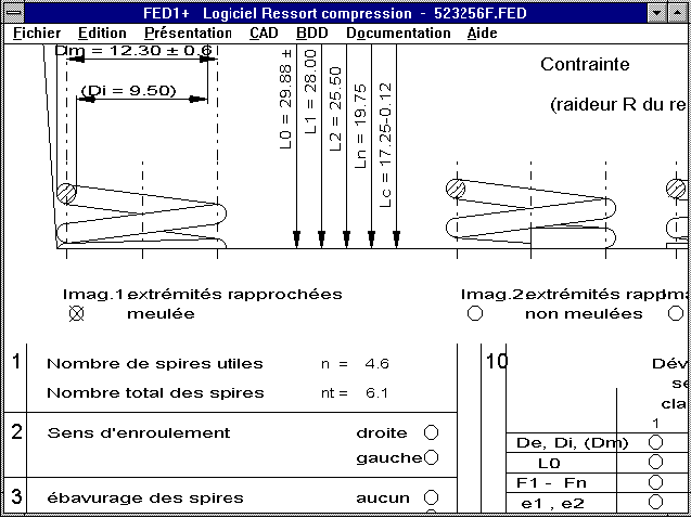 Registered users of the French versions can obtain an update for
60DM. If you have an English or a German version and wish to have
your results printed in French, you can obtain a foreign language
version for Installation on the same PC for a further 90DM.
Configurable Data Directory
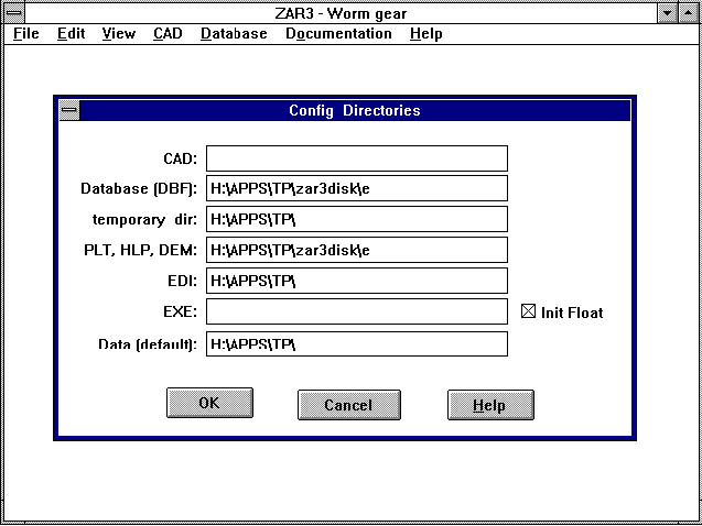 For the working directory of a program, the CFG file is loaded with
the configuration (can be changed by clicking on the program icon
with the right-hand mouse button, then "Properties->Shortcut").
Until now this was also automatically the working directory. This is
not always sensible with network versions. Each user should have his
own configuration, however the working directory for the standard
directory should be the same for all users. We recommend having the
working directory on the local hard drive (C:). Then the
start-working directory can be on a network drive. For this
suggestion I would like to thank Mr Burchard (of Kuhnke, Malente) and
Mr Bohnen (of Siemens Schaltwerk, Berlin).
Data Bases - Appending instead of Changing
Attention must be paid when making changes to data base values. When
you open old calculations you will get different results to
previously if for example material data has been changed in the data
base. This has advantages and disadvantages. On the one hand, the
modified data is automatically used in all calculations. On the
other hand, it is difficult at first glance to see why the results
are not the same as those on old calculations (especially when
somebody else changes the data base). When you make changes to the
data base, you should always inform all program users. With network
versions, it is possible to have the data base file in a
write-protected directory. Priveliges for changing and adding to the
files can be provided to certain users. A better alternative is to
add a new data record with a different name and the same contents.
Printer Configuration
The printer configuration has been divided up into text printout and
graphic printout. The way the text printout looks (printout,
standard, excerpt) can be changed under "Text Printout". Under
"Graphic Printout" the shading and zero point displacement for
drawings and diagrams can be configured.
Translation German/English by Betext
Price list |
Order |
E-Mail |
Homepage


