Info Letter No. 38 July/August 1996
by Fritz Ruoss
ZAR3 - Worm Gear
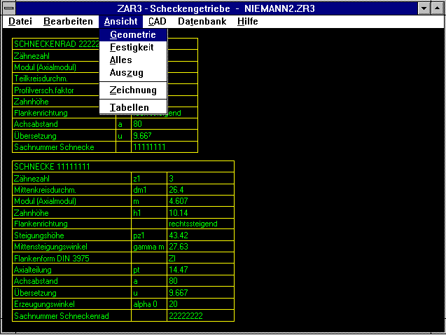
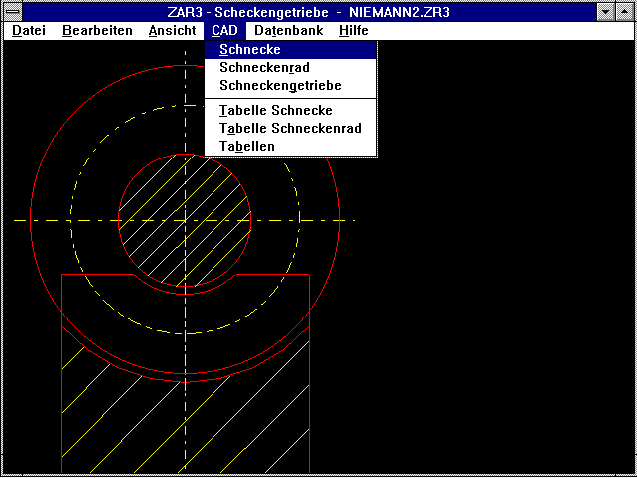 The new ZAR3 software calculates dimensions and strength of flank form worm gears, ZA, ZI, ZN or ZK, and a cross-angle of 90 degrees in accordance with DIN 3975 and Niemann/Winter. Drawings and tables
of worm and worm gear wheel can be exported to CAD via DXF or IGES files. ZAR3 is available from 15 September 1996 at a price of DM 790.
FED7 - Non-linear Cylindrical Helical Compression Spring
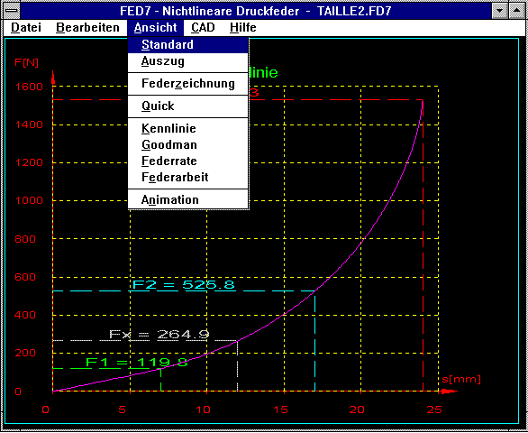 Our new software, FED7, is now available for the calculation of cylindrical helical compression springs of any shape. Similar to FED6, the spring is made up of several different sections (max. 500).
Unlike FED6, where the individual spring sections are defined by unclamped part-lengths and coil number, FED7 also allows definition of different coil diameters and wire thicknesses for the individual
coil sections. This allows calculation of compression springs with any geometry. FED7 can generate the coil section for barrel, waisted or truncated cone shaped springs. The curve for waisted springs
is particularly interesting as it uniformly progresses due to the relatively large number of coils with small coil diameters, whereas with truncated cone and barrel shaped springs the curve rises
sharply at the end. Of course FED7 also offers the facility for calculating linear and non-linear cylindrical and truncated cone shaped springs. However, FED7 is not a substitute for FED1, FED5 and
FED6 as it provides no tolerance or buckling calculation, and production drawings and dimensioning through input of forces and stroke are not possible. FED7 calculates all forces, spring paths and
shearing stresses. The curve for spring force, spring rate and spring work are displayed in a diagram and the Goodman diagram provides information about spring fatigue stress. FED7 is available from 1
October 1996 at a price of 1290 DM. The program will become a component part of the Spring Package of which the price only increases by 100 DM to a package price of 4,990 DM. If you already have our
complete Spring Package and have sent back the licence agreement, then you can obtain the new FED7 software from us until 30 June 1997 at a special price of 150 DM plus value added tax.
ZAR1+ Addendum Modification for Same Specific Gliding
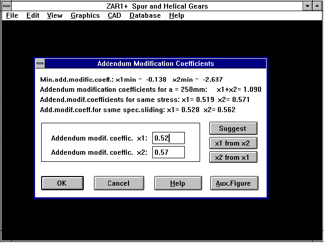 When entering the addendum modification coefficients (under "Edit->Geometry-> Standard") ZAR1+ now calculates the distribution of the addendum modification coefficients for same specific gliding as
well as the recommendation for same bending stress. The values relate to the recommended clearance (when 0 is entered for c1 and c2) because when the addendum modification is altered the outside and
root diameters of the gear change. When the addendum modification coefficients are altered during on-line input, the outside diameter stays the same and the clearance and short addendum change. Not
until you enter "0" for c1 and c2 to calculate the optimum clearance will you get the same values for the limit of the contact lines for specific gliding.
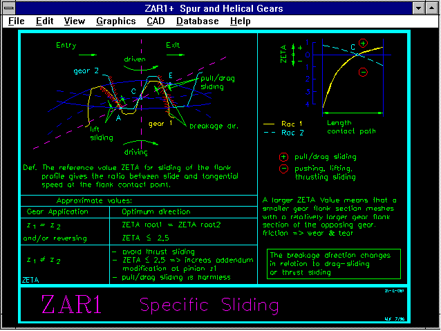
ZAR1+ Auxiliary Picture, Specific Gliding
A new auxiliary picture has been created for specific gliding,
its effects and optimization features. The file "ZETA.PLT" can
be downloaded from out mailbox or from Internet.
ZAR1+/ZAR2/ZAR3 Material Data Base
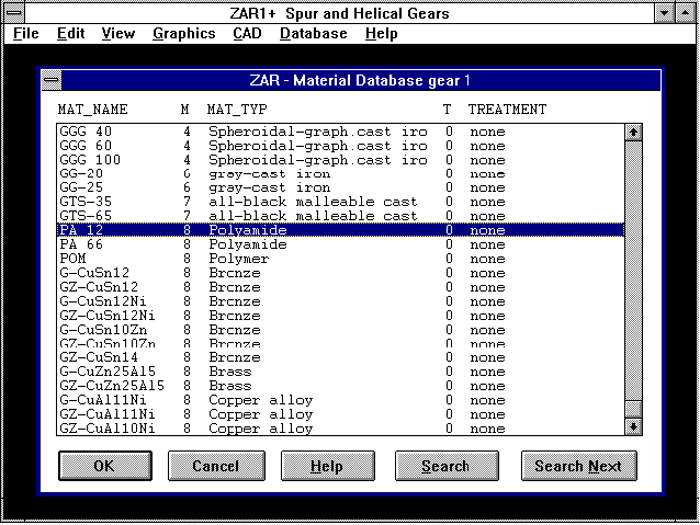 The material data base for ZAR3 has been extended with the materials bronze, brass and cooper alloys. The material values for PA12, PA66 and POM have also been included. The extended data base file
ZARWST.DBF can be downloaded from our mailbox or Internet (User: Info38, Password: Schnecke).
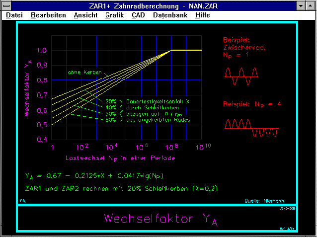
Approximation Equation in Auxiliary Picture YA
The equation for the calculation of YA from Niemann "YA = 0,67 - 0.2125X + 0,0417 lg Np" is not quite correct for Np > 100, as this doesn't match the Niemann diagram. For this reason we have changed
our gearing program so that YA=1 when (with Np>=1e9) a value smaller than "1" is entered. Many thanks to Mr Schaarschmidt for the information.
WL1+ Side View Schematic
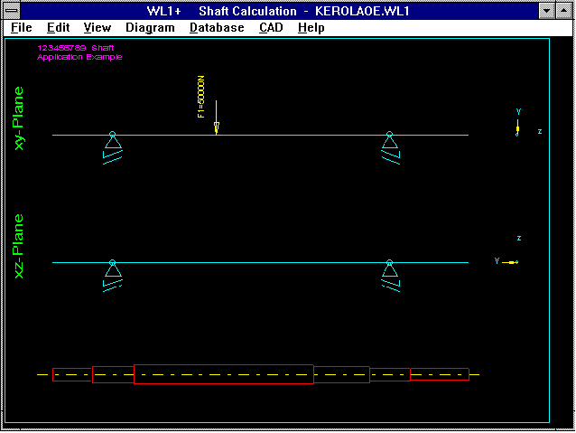 The schematic shows shearing forces and stretch loads with direction of the effect shown in the yz plane. This provides a better overview (especially with skew attacking forces) and allows better
control of the entered angle and neg/pos sign.
WL1+ Shaft Dimensioning
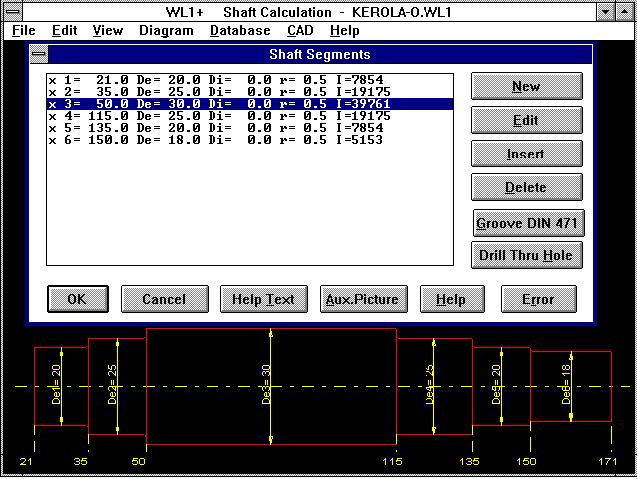 When the shaft is input, the shaft drawing shows diameter and indices as well as the coordinate measurements in the x axis. The bearing drawing includes the description of the bearing. The shaft can
be exported to CAD with or without dimensions. I would like to thank Mr Hilmar Mller of Mller's Construction Office in Wollbach for this suggestion.
TOL1 - Dimension Chain
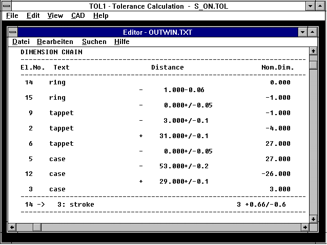 The dimension chain for a critical interval can now be output as a list as well as graphically presented.
TOL1 - Cross Reference
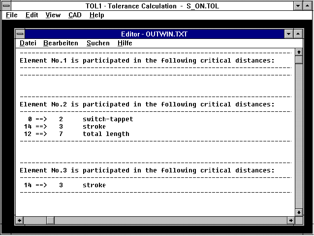 If you would like to know in which critical interval a certain element is included, you can have TOL1 print out a list under the new option "Cross Reference".
TOL1 - More Text
A remark of up to 18 characters can now be included with each element (previously only 10 characters).
Graphic Print Out on Full Page
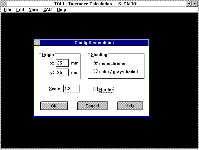 Previously the Windows program "screen dump" sideways print out of drawings and diagrams didn't always produce a drawing of full size. With our new versions you can enter the scale and zero point
displacement under "Configuration->Printer". A standard setting for a sideways DIN A4 page is a scale of 1.2 and a zero point displacement of 25/25. If you hilite the "border" box, then the graphic
will be printed with a border (with a double click of the mouse in the drawing area, a footer showing file name, date, etc., will also be included).
Printer Settings
The menu item "File->Printer Setting" has been dropped from all Windows programs. Changes to printer type and print settings can now be accomplished directly under "Print".
ZAR2 - Bevel Gear Tables
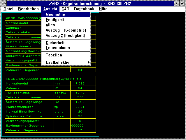 With ZAR2 you can display tables of pinion and bevel gears on screen and export them to CAD via DXF and IGES files. When a file is opened, both tables are automatically displayed.
FED1..FED6: Error Messages due to Tolerances
During calculation it can occur that the spring force tolerance F1 is greater than the spring force itself. This is not a program error, but can be logically explained. When the spring path in
position 1 is relatively small in relation to the usable spring path, this case can easily occur. For F1=0 the tolerance cannot be 0! The new programs now provide a warning when in extreme cases the
taking into account of production tolerances results in a spring force F1 smaller than 0, or a spring force F2 greater than Fn or even Fc.
FED1,FED5,FED6: Guide bar/bush
The diameter of the guide bar or bush is rounded up or down to the next tenth of a millimeter in the production drawing.
ZAR1 - Kv in Interim Area
The dynamic factor Kv is calculated differently, dependent upon the location of the pinion torque in relation to the resonance frequence. Until now the dynamic factor in the area between main
resonance and upper critical area has been calculated wrongly in ZAR1/ZAR1+ (interim area 1.15Text Printout under Windows
There are four ways of printing out result lists under Windows. The most awkward way (which is apparently used the most) is printing out under "Print-File" in the notepad editor.
- 1. Output to Text Printer: This option can be used when you have a laser, inkjet or needle printer with ASCII character set installed. The printer interface is configured under
File-Setting-Printer (Text Printer). The printer must be set to the same character set as the PC (PC-8 for HP Laserjet). Output to postscript printer is not possible here!
- 2. Output to Windows Printer: All printers configured under Windows can be selected. The printer defined under System Control will show as default printer. Settings, such as long or sideways
format, can be made in the printer selection window under "Options".
- 3. Output to Screen: For screen ouput the result list is loaded into the Notepad Editor by Windows. With the editor you can make a printout (not recommended), before you do this you must set the
margins to 0 and probably define a page break under "Page Settings".
- 4. Output to External Text Program: You can define any text program as output program with the new versions from June 1996. However, a non-proportional typeface such as courier must be selected.
WL1+ Radial Thrust Bearing
During calculation of shafts with taper roller bearings as radial thrust bearings an erroneous value was calculated during calculation of the bending moment from the axial force components of the
taper roller bearing. The error has been corrected. Please check in your old calculations whether or not the bending moment was correctly calculated. I would like to thank Mr Hofmann of Alpha
Getriebebau in Ingersheim and Mr Nyhof of Voith Turbo in Heidenheim for pointing this out.
TOL1 - Insert Critical Distance
Entering a new critical distance caused the elements following to be altered. The error has been corrected. I would like to thank Mr Petri of Thomas-Magnete in Herborn.
Help Degree 0
In many of our programs a result diagram is automatically displayed when quitting "input". In the spring programs the "Quick Ouput" is displayed and in the shaft programs the shaft is displayed after
each input section is completed. If you do not want this to happen (for example when your computer takes a long time to complete the screen image) you can reconfigure to Help Degree 0, then the screen
output will automatically be suppressed. Our Internet pages are now finished under "http://www.hexagon.de". You can now display all HEXAGON software leaflets and brochures on screen and download all
German and English demo versions.
Users of HEXAGON software in Internet
A list of HEXAGON software users appears in our Internet pages. If you have your own domain, homepage and/or E-mail address in Internet, please let us know the URL then we will refer to it with a
Hyperlink. Please also let us know if you wish not to be listed as a HEXAGON software user and we will remove this information.
HEXAGON Industriesoftware GmbH
Stiegelstrasse 8
D-73230 Kirchheim/Teck (Germany)
Telephone: 07021-59578
Fax: 07021-59986
Mailbox BBS: 07021-480015 (Modem 28800..2400bps)
Mailbox BBS: 07021-959242 (ISDN 64000bps)
Director: Fritz Ruoss
Return


 With ZAR2 you can display tables of pinion and bevel gears on screen and export them to CAD via DXF and IGES files. When a file is opened, both tables are automatically displayed.