 | English
| Deutsch
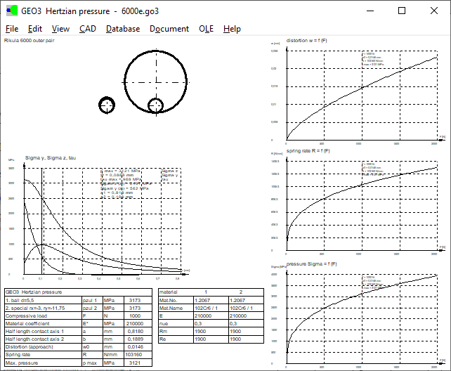
GEO3: Quick3 View
In the Quick3 view, all data are displayed on the graphic screen, with drawings and diagrams of deformation, pressure, spring rate, and stress spectrum under the surface.

GEO3: Elastic compression of ball or roller
If the Hertzian pressure between spheres or cylinders is to be determined, GEO3 now also calculates the compression of the bodies, as well as the total spring rate, taking into account the compression of the ball or cylinder.
Elastic compression (Hooke's law): s = F * L / (A * E)
Average area cylinder: A = ders * L (ders = 0.7 * d)
Average area sphere: A = pi / 4 * ders² (ders = 0.6 * d)
Spring rate R = F / s = 1 / (1 / R1 + 1 / R2))
GEO3: Quick Input
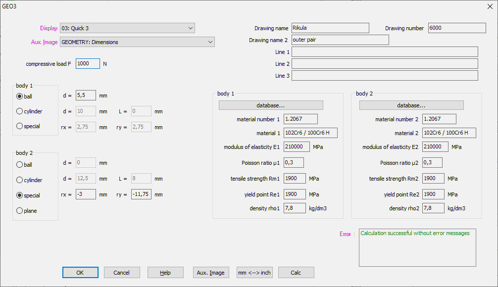
In the quick input, all input windows are integrated into one large window, in the background you can display all possible graphic windows with calculation results and diagrams.
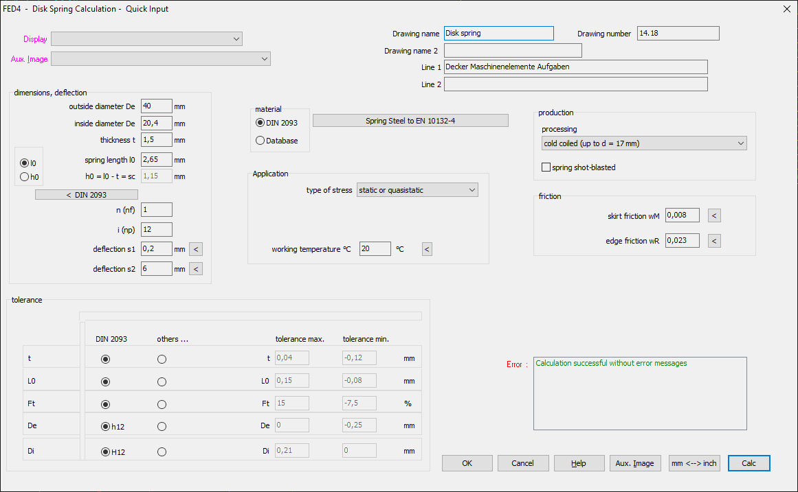
FED4: Quick Input
In the new Quick input of the disk spring design software, all input windows are combined into one large window, in the background you can display all possible graphic windows with calculation results and diagrams.
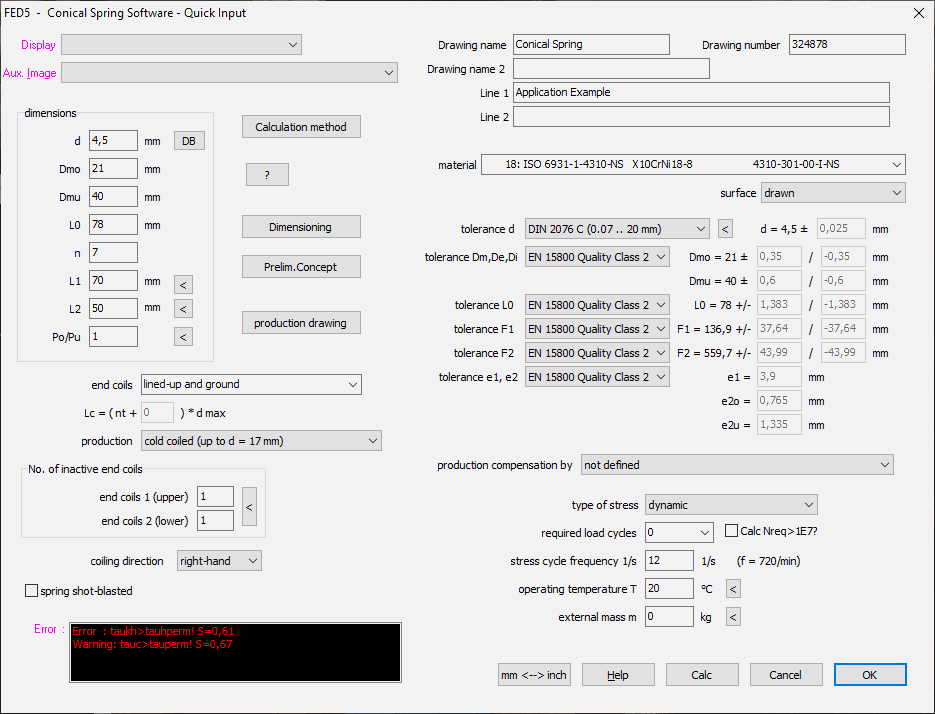
FED5: Quick Input
New Quick input: Enter all data in one large window, check results in background graphic.
FED2+, ZAR2, ZAR6, ZAR1W, WL1+, WN1, TR1, FED4, FED5, FED10: Expert Mode
In the programs with quick input, the "Expert Mode" can be switched off in the Help menu. New users and occasional users should switch off the "Expert Mode", which makes it easier to use the software because only the most important options are displayed in the menu. Under "Edit" only "Quick Input". "Database" and "OLE" menu are completely hidden in this settings.
WN2, WN2+: Data field to DIN 5480-1:2006 modified
According to DIN 5480-1: 2006 (machining), the tolerance of the root diameter is:
Adf2 = (0.2m + 1.73 (Ae + TG)) and Adf1 = - (0.2m + 1.73 * (- As + TG)).
In WN2, the tooth gap tolerances of the selected tolerance field were used until now. In fact, the tolerances from series 9H and a11 must always be used. The table also contains the theoretical nominal dimensions of the tip and root diameter. Instead of the calculated maximum diameter. This has been corrected, the root diameter tolerances are now even greater. Nothing changes in the gear data. The tip and root circle tolerances from tooth thickness dimensions and tooth height factors are much smaller and are well within the DIN 5480 tolerances. According to Chapter 7.1 in DIN5480-1: 2006, the dimensions of the root diameter must be reduced if hfp = 0.6m or hfp = 0.65m instead of hfp = 0.55m. Adapted formulas:
Adf1 = - (0.2m + 1.73 * (- As + TG)) + 2 * (hfp-0.55 * m) for hfp / m = 0.55 .. 0.65)
Adf2 = (0.2 * m + 1.73 * (Ae + TG)) - 2 * (hfp-0.55 * m)
If a fit (j .. v) with overlap is selected, the largest dimension is outside the DIN 5480 dimensions. Because according to DIN 5480 the nominal dimension is used as the largest dimension. It is a good thing that the information given in DIN 5480 Table 5 is only "recommended tolerances and dimensions for tip and root diameter".
WN2, WN2+: Gearing data table
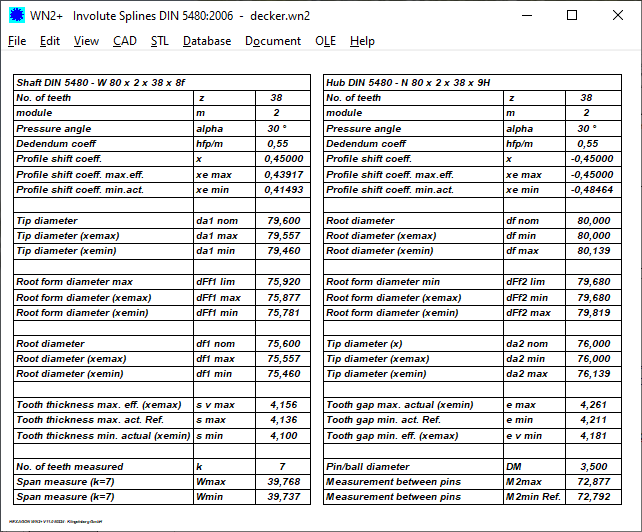
In addition to "Tables DIN 5480: 1991" and "Table DIN 5480: 2006" there is now "Table gear". The difference to the DIN 5480 tables is that for tip and root diameter there are no arbitrarily defined dimensions, but the individually calculated maximum and minimum dimensions of tip and root diameter with flank centering from tooth thickness dimensions and tooth height factors. The profile shift factors x, xemax, xemin (nom / max / min) are also output.
WN2, WN2+: Calculate form interference
In DIN 5480-1: 2006 it is stated how large the root form circle diameter dFf should be (since [mating gear] + 2 * cFmin), but not how large it actually is. DFf is calculated from head height factors (haP = 0.45m, hfP = 0.55m .. 0.65m), root rounding factor (0.16 m), profile shift and tooth thickness dimensions.
In WN2 +, cF1,2 is now also calculated, the distance from the start of the involute to the tip diameter of the mating gear. Error messages are displayed if cF <0 or cF <cFmin.
Then you either have to reduce the fillet root radius or modify the tooth height factors.
       ----------------------------------------------------------------------
       Min interference util.            cF min   mm              0,040
       ----------------------------------------------------------------------
       CF1,2 = -(da1,2 + dffmax2,1)/2    cF       mm         0,062      0,062
       ----------------------------------------------------------------------
       Root form diameter lim            dFflim   mm        75,920    -79,680
       ----------------------------------------------------------------------
       Root form diameter max            dFfmax   mm        75,877    -79,680
       ----------------------------------------------------------------------
       Root form diameter min            dFfmin   mm        75,781    -79,819
       ----------------------------------------------------------------------
SR1 Tip: Bolted joint with countersunk screw head (cylindrical or conical)
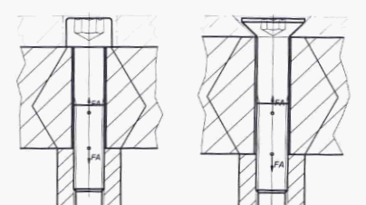
If a cylinder head screw is countersunk in the first clamping plate, the height of the first clamping plate must be reduced by the height of the screw head or the countersink, because the clamping plate is not clamped in the area of the countersink.
It is similar with countersunk screws. Here, however, the clamping plate is at least partially clamped in the area of the countersink, so the height of the clamping plate can only be shortened by part of the head height. In VDI 2230 there are no countersunk screws, in SR1 countersunk screws are therefore calculated like cylinder screws. The graphic representation with the countersunk head on the clamping plate is corresponding.
See example 1 in VDI 2230: Length of clamping plate L1 = height of piston including countersink - height of countersink = 55mm –13mm = 42mm.
Same application with countersunk screw instead of hexagon socket screw: length of clamping plate L1 = height of piston including countersink - height of countersink = 55mm - 8mm = 47mm.
All Programs: Input window sizeable yes/no?
So far you could change the size of all input windows. This is only absolutely necessary if the graphics settings are not yet correct. It was annoying that the size was unintentionally changed when the mouse was "swiping past". Therefore you can now set "sizeable" in the dialog window under "File \ Settings \ Graphics". In the standard setting, "sizeable" is off.
Only the database window, the configuration window and the preview window under "File \ Open (table)" can always be opened.

Update: Install new release together with previous release
If you don't want to replace the old version with the new one during an update, you can use the old and new version alternately. With a single user license, the new version is installed in a different folder on the same computer. With a network floating license, the exe program file of the new or old version is renamed and copied to the same directory (e.g. wfed1.exe and wfed1neu.exe). The old and new versions then run under the same key code and the same license.