 | English
| Deutsch
FED3+: Quick Input

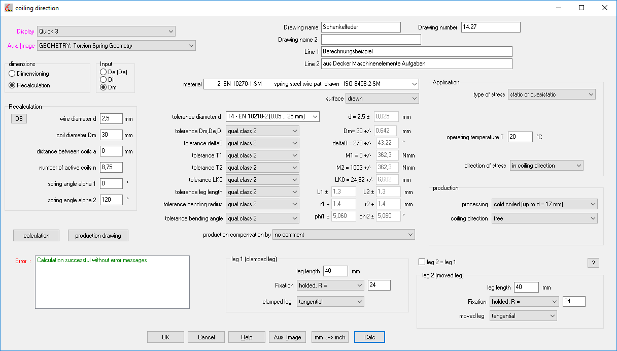
In the Quick Entry, all input data has been summarized in just one dialog box. Use Calc or Enter to calculate the torsion spring and display the results in the background window.
FED1, 5,6,7,17: wire mass (gross weight of the spring)
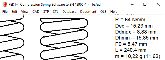
Since version 28.1, the weight of the spring has taken into account ground end coils and the abraded material has been deducted from wire weight. However, spring manufacturers need for the procurement of material also the weight of the required spring wire, therefore, the gross weight is now output in the expression in addition. In the Quick3 view, the weight of the non-ground spring is displayed in parenthesis.
FED4,9,10,13,14,15,16: Goodman diagram for spring steel strip according to EN 10132-4
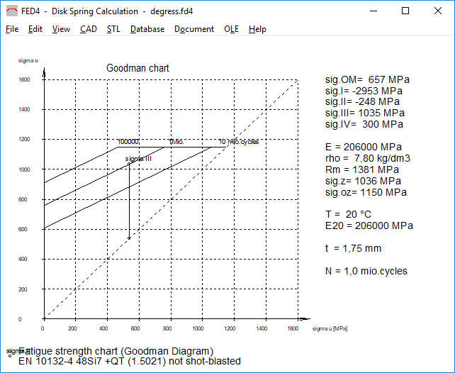
For spring steel strip according to EN 10132-4 from the material database fed9wst.dbf a Goodman diagram is now displayed. The fatigue data is available from DIN 2093: 2013-12 for disc springs.
FED9,10,13,14,15,16: spring steel strip 1.4310 and 1.4368 in fed9wst.dbf
Spring strip made of stainless steel is available in various levels of tensile strength classes according to EN10151: 2002: from + C700 (Rm = 700..850MPa) to + C1900 (Rm = 1900-2200 MPa).
1.4310 is available from + C850 to + C1900, 1.4568 is available from + C1000 to + C1700,
1.4401 is available from + C700 to + C1300.
In the spring material database fed9wst.dbf the 3 stainless spring steel strips have been replaced:
1.4310 C + T in 1.4310 + C1900
1.4568 C + T in 1.4568 + C1700
1.4401 C + T in 1.4401 + C1300
After heat treatment, the tensile strength becomes about 5% (1.4310) to 20% (1.4568) higher. The tensile strength of 1.4568 + C1700 is higher than for 1.4310 + C1900 after heat treatment.
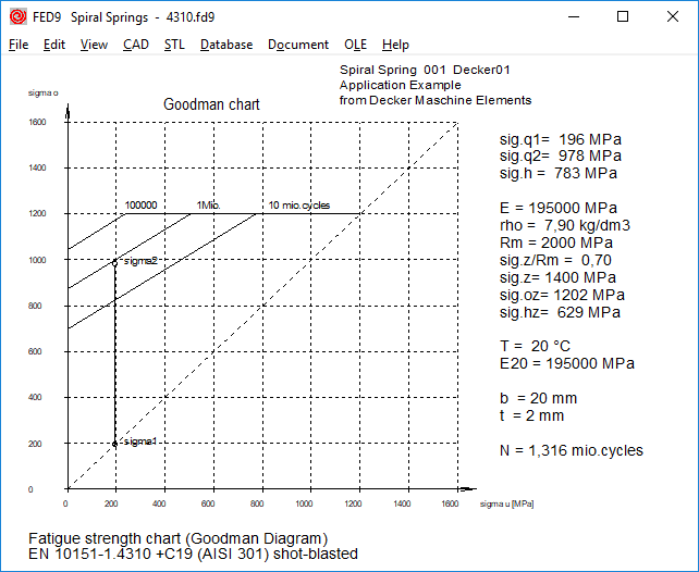
Compared to the previous data, tensile strength and fatigue strength values for 1.4310 C + T and 1.4568 C + T are smaller for small sheet thickness. With spring steel band, the dependence of the strength values on the strip thickness is less than with spring wire the dependence on the wire diameter.
FED14: Stress correction coefficient q for dynamic application
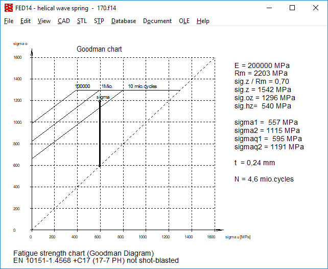
Similar than in the other coil spring programs, a stress correction factor q is now also used in FED14 under dynamic load. As in FED3 +, q is calculated according to Göhner: q = 1 + 0.87 / w + 0.642 / w² or with the approximation formula according to EN 13906-3: q = (w + 0.07) / (w-0.75) with the winding ratio w = Dm / b
From this, the corrected bending stresses are calculated:
Sigmaq1 = q * sigma1
Sigmaq2 = q * sigma2
In the Goodman diagram, sigmaq1 and sigmaq2 are plotted instead of sigma1 and sigma2, which results in a shorter lifetime.
FED1,2,3,5,6,7,8,11,17: Spring wire: "Roeslau extra" and "Roeslau extra-extra" in fedwst.dbf
Piano string steel spring wire "Röslau-Extra" and high-strength piano string steel spring steel wire "Röslau-Extra-Extra" were added to the spring wire material database fedwst.dbf. The tensile strength is higher than for EN 10270-1 SH. Fatigue values are not available. Tolerance for the wire diameter corresponds to DIN 2076C.
LG1, ZAR5, WL1+: Permissible axial load for cylindrical roller bearings NUP and NJ
The permissible dynamic axial load capacity Faz is calculated using
Faz = k1 * C0 * 1E4 / (n * (d + D))
At low speed, Faz had been overstated. In this case, a limitation to Faz = 1.2 * D² applies due to the permissible surface pressure now.
GEO4 – Spline function for cam geometry
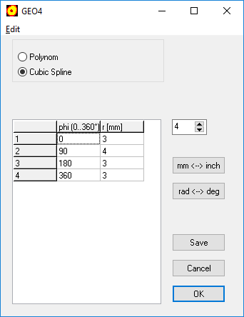
In GEO4, you can already enter the base points of the cam curve and generate a polynomial function from them. Now you can connect the entered coordinates alternatively with cubic splines.
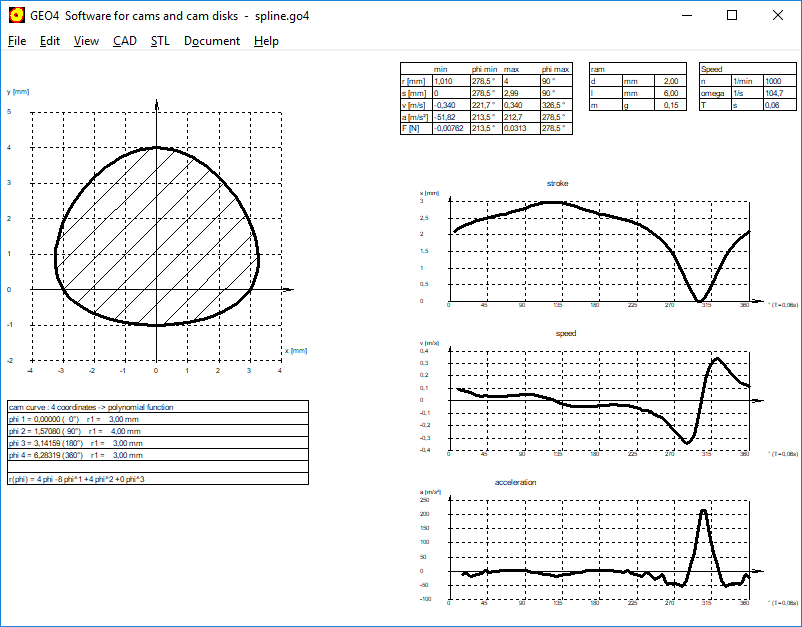
There is also a new demo version of GEO4 now at www.hexagon.de/down_e.htm.
ZARXP: face width and bore diameter added in table
In order to be able to produce the generated tooth profile as a gear wheel directly on 3D printers, the input had recently been supplemented with face width and bore diameter.
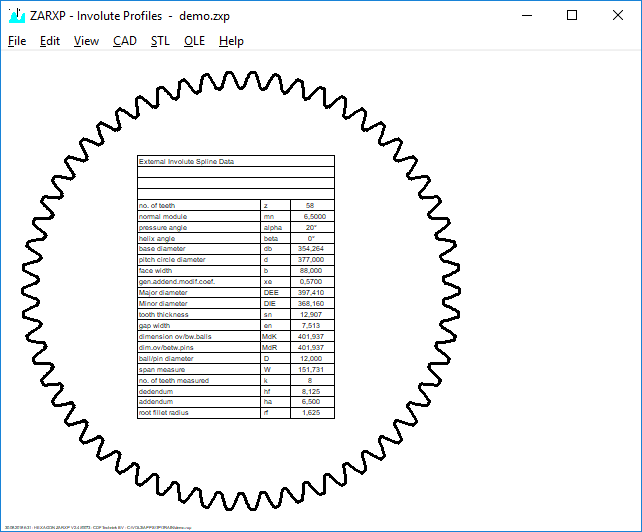
In the Quick view and in the printout, tooth width and bore diameter (or outer diameter for internal toothing) are now also output.
ZAR3+: External diameter de2 = da2 + 2 mt2
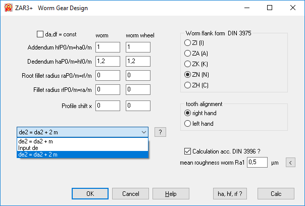
The outer diameter de2 of the worm wheel can be entered directly or can be calculated with "de2 = da2 + mt2". The tangential modulus mt2 of the worm wheel is the axial modulus mx1 of the worm, usually designated only as modulus m. Now you can also calculate "de2 = da2 + 2 m". Since the recommended tooth width b2 of the worm wheel is also based on de2 = da2 + 2m, this is the new default setting.
ZAR3+: Tooth width b2 and wheel width bH of worm wheel
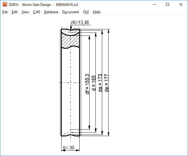
In ZAR3 + the worm wheel is drawn with the tooth width b2. In most cases, the worm wheel width b2R or b2H is greater than the tooth width b2, so now in the drawing, a wider shape of the worm wheel is indicated. The final design with chamfers and radii is left to the designer.
Tip: Updates and database modifications
An update of HEXAGON software is 10 times faster than a Windows 10 update. During the update, the new files are simply installed over the old files of the same name in the same path. It will only be complicated if you have modified databases and want to keep the changes. Then you either have to sync changed DBF files or keep your old DBF files.
If you want to extend the databases, you can also send us the data. If useful, we'll expand the .dbf files, and your data will be included in all future updates for you and all other users.