 | English
| Deutsch
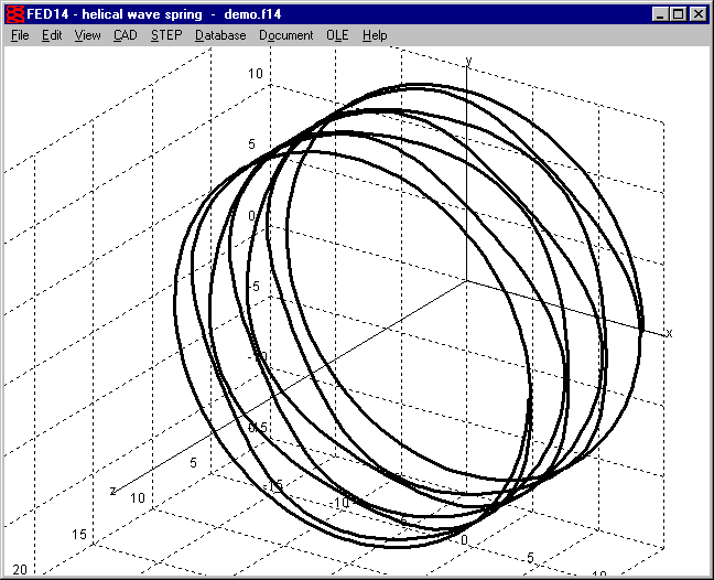
FED14: 3D Centerline of Helical Wave Spring

3D centerline of helical wave spring can now be generated as 3D drawing to be exported into CAD as DXF, IGES, STEP or TXT file.
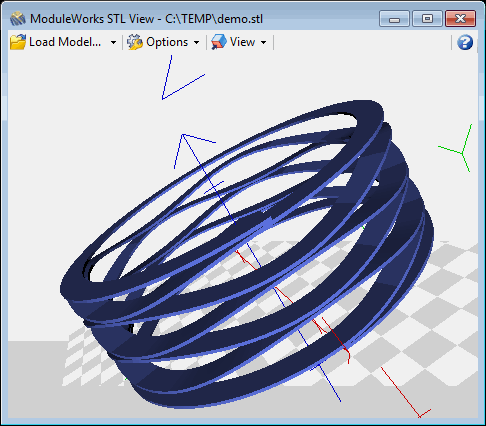
FED14: STL Export
A 3D model of the helical wave spring can be generated as STL file.
FED1+: Temperature Table
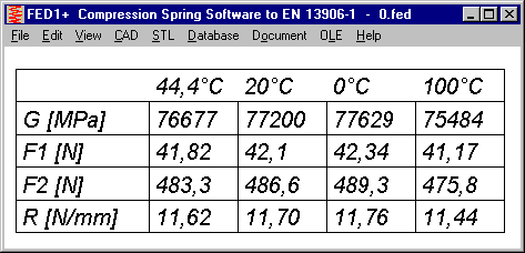
A table with spring properties for four different temperatures can be shown now at View -> Temperature -> Table:
Table includes temperature-dependent data shear module G, spring loads F1, F2, as well as F1,48h and F2,48h after relaxation, and spring rate R.
Quick4 view includes the temperature table, if operating temperature is different than 20°C.
Quick3 view, from now on shows spring load F2,48h only if springs "not set" or "free" was selected at "Edit -> Production Drawing". If the compression spring was pre-set, remaining relaxation is much lower than calculated, and therefore no longer listed in Quick3 and Quick4 view.
FED3+: Diameter of Mandrel and Bore
According to DIN 2194, test mandrel diameter DP is calculated. Maximum diameter of mandrel and minimum diameter of bore had been calculated according to this formula, too. Now, max mandrel and min bore diameter are calculated without 5% buffer, but with wire diameter tolerance.
Ddmax2 = Di2 – AD – Ad (mandrel until alpha2) and Ddmaxn = Din – AD – Ad (mandrel until alpha n)
DHmin = De + AD + Ad (bore)

As alternative, you can enter mandrel diameter with tolerance at Edit->Production Drawing". List of available pre-settings was enlarged: select between Dd<=DP, Dd<=Ddmax2, Dd<=Ddmaxn, or with ".." input mandrel diameter and tolerance.
FED4: Spring rate of packed disk springs
In FED4 you can calculate disk springs as well as disk spring packages. For number of spring packages i > 1, spring loads were calculated correct, but spring rate remained unchanged, this was corrected now (i = number of spring packs, n = disk springs per pack):
Spring load of spring pack compared with single spring: F = Fi * n
Spring rate: R = Ri * n / i
Spring Work: W = Wi * n * i
Thanks to Mr. Erhardt of Hilti for the hint.
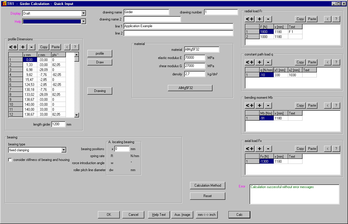
TR1: Quick Input for Girder Calculation
In a new Quick Input dialogue window you now can enter all dimensions, load, material and bearing data.
ZAR2: Quick Input for Spiral Bevel Gears (Klingelnberg Cyclopalloide)
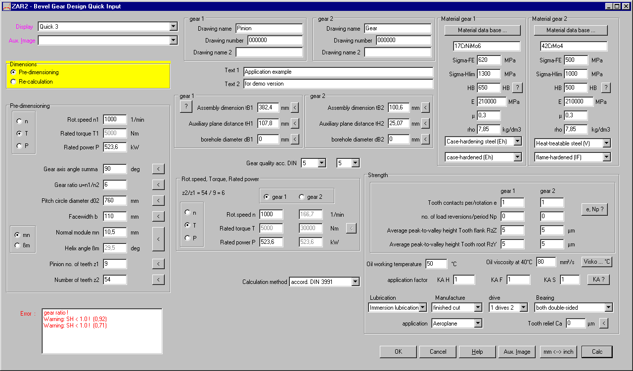
New Quick Input allows input of all dimensions, tolerances, assembly dimensions, material, drive data, lubrication and strength calculation data in only one dialogue window now.
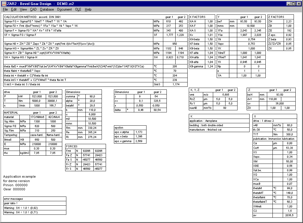
ZAR2, ZAR6: View Strength Calculation with Formulae and Factors
Similar as in ZAR1+, in ZAR2 and ZAR6 a new screen was created with essential formulas, factors and results of strength calculation according to DIN 3991.
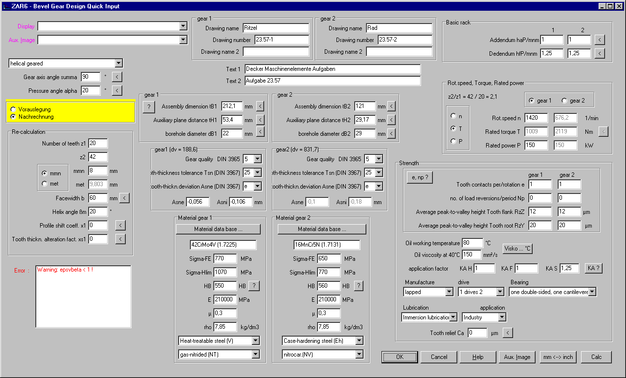
ZAR6: Quick Input for Bevel Gear Design
Enter all dimensions, tolerances, assembly data, material, drive data and data for strength calculation in only one dialogue window.
ZAR1+, ZAR5, ZAR7, ZAR8: Measuring circle drawn according to xe settings
Measuring circle in tooth gap drawing was drawn in tolerance center until now, as this is the default setting. If you modified tooth drawing by means of profile shift coefficient xe, position of measure circle remained unchanged. But now, dimensions over balls/pins are calculated for the actual setting and measuring circle is drawn equivalent to this setting.
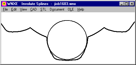
ZAR1+, ZARXP, ZAR1W,WN2+,WN4,WN5,WN10,WNXE: Button "Tooth gap + DM"

A new button "tooth gap + DM" in the input window draws tooth gap with measuring circle in the background window. So you can easily test different ball and pin diameters. The suggested value according to DIN 3960 is not always suitable for gears with small tooth height (involute splines), calculated diameter must be checked. By means of the drawing you can evaluate if a flattened pin or ball must be used.
ZARXP, WNXE: Minimum and Maximum values of Dimensions over Pins or Balls
Input of dimension over pins/balls for iterative calculation of profile shift coefficient xe was improved in ZARXP and WNXE. Allowed input zone for internal gears and splines was enlarged, and if overriding allowed zone you get error messages MR>MRmax, MR<MRmin, MK>MKmax, MK<MKmin. Please consider negative signs if you calculate internal gears (-2 is smaller than –1).
FED1+, SR1+, WL1+, FED10: Error Box in Quick Input Window

New box with error messages at Quick Input: Click into error message to get description and remedy displayed as hint.
ZAR1+, ZAR1W, ZARXP: Profile drawn continuous
By inserting teeth as block into the drawing, gear wheels not always were drawn in one curve. This cannot be seen in the drawing, but if you convert the profile drawing into CNC code this can be used without optimization now. By means of our DXFMAN software, tooth profile can be converted into one polyline, to be used in GEO1+ for example to calculate area, mass and area moments of inertia.
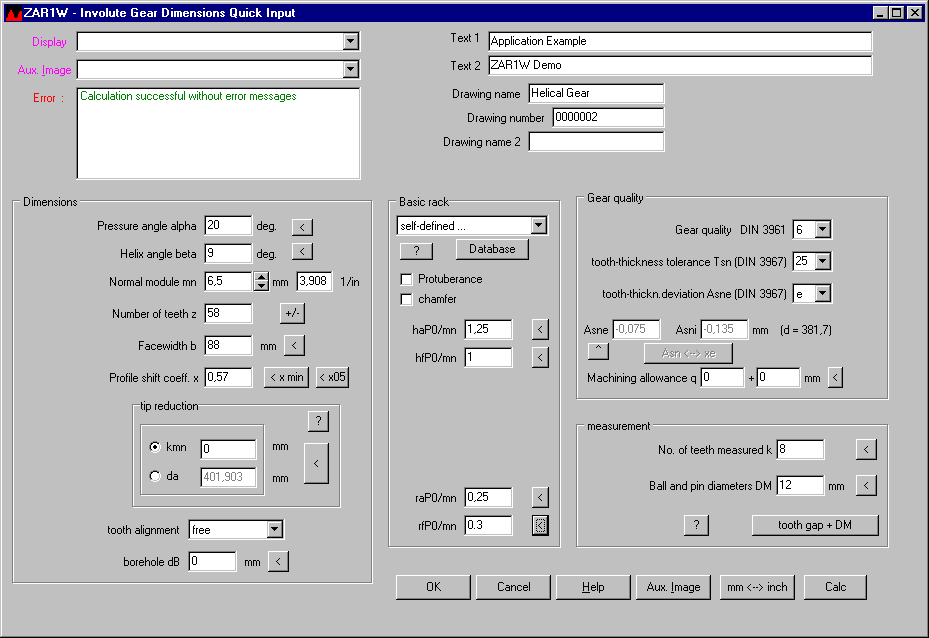
ZAR1W: Quick Input
ZAR1W calculates dimensions and tolerances of one gear wheel. Other as in ZAR1+, in ZAR1W you calculate one gear wheel, no gear pair. No center distance, no strength calculation. ZAR1W is well suited for gear manufacturers, few input data are enough to get all dimensions and a profile drawing. New in ZAR1W is Quick Input with all input data in one dialogue window. With "Calc" button or "Enter" key, gear wheel is recalculated and result graphic is actualized in the background window.
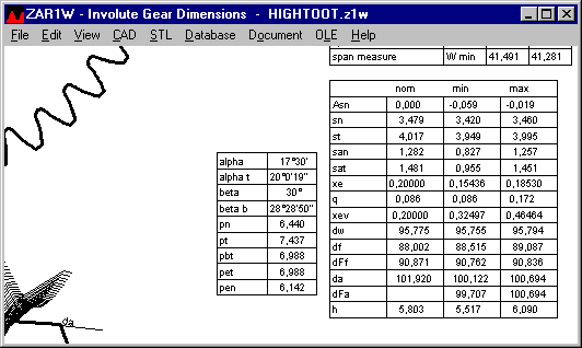
ZAR1W: Additional Table in Quick4 View
Two tables with additional dimensions (nominal/min/max) have been added to Quick4 View.
HPGL-Manager, DXF-Manager: DXF Polyline

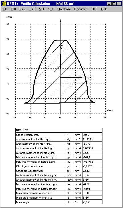
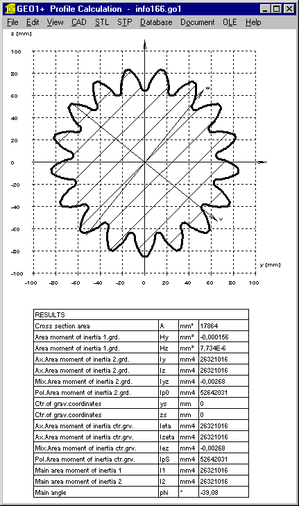
For conversion of a profile drawing into DXF you can set a new Option "DXF Polyline?" to create a dxf drawing which consists of only one drawing element, one polyline. Of course, this makes sense only if the drawing is a continuous profile, a gear profile drawing of ZAR1+ for example, where a teeth is defined as block and inserted z times. By conversion from DXF into DXF, blocks are removed and tooth profile drawn as one polyline. Example applications: convert into CNC track, or load into CAD and extrude as 3D body, or import with GEO1+ for calculation of area and area moments of inertia. If you import a gear wheel DXF file of ZAR1+ into GEO1+, one teeth will be loaded and calculated. If you convert the file by means of DXFMAN and "DXF Polyline?" option, you can import the complete gear wheel profile into GEO1+.
GEO1+: Mirror and Copy
By button "Transform.", profile coordinates can be moved, turned, mirrored and direction inverted. A new option "Mirror and Copy" has been added.. This eases input of symmetric profiles. Design a half of the profile, 2nd half "mirror and copy".
GEO1+: Create 3D STL files from 2D GEO1 Profiles
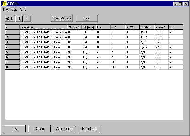
At "Edit -> 3D Layer" you can select up to 100 GEO1 files and assemble to a 3D body by input of profile height and position. Next you can create a STL file for 3D printing. For a gear wheel with inner internal spline, for example, 2 files are required: gear profile of ZAR1+ or ZAR1W or ZARXP, and inner involute spline profile of WN4 or WNXE.
For each GEO1 element, you can define position, scale and direction. This is very practical, so you can work with only few base profiles. For example, a circle with diameter of 1mm can be used for each cylinder and bore, because diameter is entered as scale. With direction "+" as cylinder and inverse direction "-" as cylindrical bore.
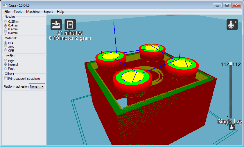
Example: Lego block made from only 2 base elements: circle (6x) and square (2x).
SR1: Yield Point at higher temperature
If you enter a working temperature other than reference temperature, SR1 calculates tensile strength Rm, yield point Rp0.2 and permissible pressure pG for working temperature from database at "Database\Material\Bolt,Plates\Rp0.2=f(T)". If the selected material cannot be found in the database, SR1+ uses this formula for approximated calculation of the yield point:
Rp(T) = Rp*(1.018-T/1120)
Tensile strength and permissible pressure at temperature are calculated with the same coefficient:
Rm(T)=Rm20*Rp(T)/Rp20
pG(T)=pG20*Rp(T)/Rp20.
All Programs: Zoom Screen Graphic with Mouse Wheel
As alternative to keys + and – you now can use mouse wheel to enlarge or reduce size of screen graphic.

Tip: Exec DXF, IGS, STP, STL software directly
If "Exec CAD App" is checked at "File\Settings\CAD\", the installed software to edit or view CAD files or STL files is executed to open the generated CAD file. If no application is assigned to the file extension (DXF,IGS,STP,STL), maybe you get an error message such as "cannot open file" or "no certificate". To avoid the error message, uncheck "Exec CAD App?", then save configuration.
At "File\Settings\Directories" you can configure the folder for CAD files.

Tip: Spring Calculations with different shear module
Our spring software calculates with shear module G=82000MPa for spring wire DM,DH,SM,SH. EN 10270-1 and EN 13906, however, use G= 81500 MPa. The difference of 0.6% results in an equivalent difference at load and stress. We use G=82000MPa since decades, because customers claim that these data are exact. To compare results with shear module G=81500 according to EN, you have several possibilities:
Option 3 is not recommended: On a later update, your modified database fedwst.dbf may be overwritten, if you do not take care about.
Other materials with deviations to EN standards: spring wire according to EN 13906-2: G=79500 MPa. HEXAGON software uses G=79500 for FDC, FDCrV and FDSiCr. But shear module G for VDC is a bit higher and for VDCrV and VDSiCr a bit lower.
Tip: Save default settings in NULL file
Your individually preferred materials, tolerances, dimensions, .. can be saved in a NULL file. NULL is the file name.
Example: In SR1, material database mat_p_1.dbf for clamping plates and material 10.9 for bolts and friction coefficients 0.1 should be set by default.
Then start a new calculation, input default data and one clamping plate, then save with file name "null". If you start SR1+ next time, it opens file null.sr1 automatically, if exist.