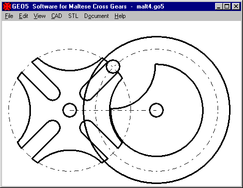

GEO5 New Software for Geneva Drive Mechanism (Maltese Cross Drive)
Our new software calculates dimensions of Geneva drive mechanism with 3, 4, 5, 6, 8 or more beams.

In an animation you can watch the motion of driving wheel and Maltese cross wheel on screen. Curves of travel, speed and acceleration are shown as diagram.
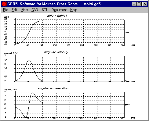
Finally you can print all components of the Geneva drive (except bolts and shafts) on your 3D printer and assemble a functioning model. GEO5 is available now for 218 EUR.
FED6 Input Dm, Di, De

Same as in FED1+, you now can choose in FED6 between input of mean coil diameter Dm, external coil diameter De, or inner coil diameter Di. The selected diameter is printed with tolerances.
FED6 Input either L0 or aw or P for coil sections
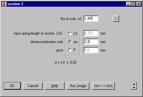
As alternative to unloaded length of coil section, you can now enter distance between coils aW or pitch P of each coil section. Input influences table in production drawing: selected value is printed in the table.
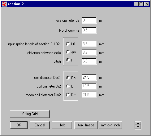
FED7 Input L0 or aW or P and Dm, Di, De for coil sections
Input of coil sections became more flexible in FED7: as alternative to unloaded length L0i of each coil section, you can enter distance between coils awi or coil pitch Pi. And as alternative to center coil diameter Dm you can enter inner coil diameter Di or external coil diameter De. Input influences production drawing: chosen values are printed in the coil section table.
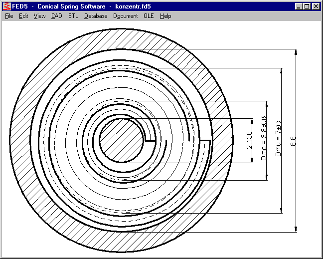
FED5: Upper View
By means of the new top view in FED5 you can evaluate guidance of the conical spring by mandrel and bore, especially for concentric end coils. Drawing includes mandrel and bore together with the end coils of the conical spring. Active coils are indicated as spiral center line.
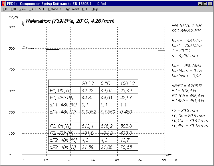
FED1+: Relaxation table
In the relaxation diagram f(t), spring load F1 was wrong, printed as F2. Error was corrected, thanks to Mr. Balic of Joos springs. If you received your software between August 2016 and April 2017 and you get wrong value for F1 in relaxation table, please request a free update.
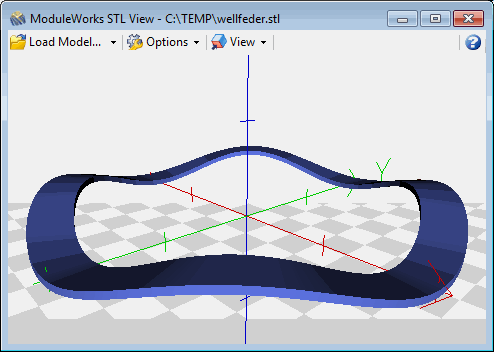
FED13 - 3D STL-Model
A 3D model of a wave spring can be generated as STL file and displayed with a 3D viewer or printed with a 3D printer.
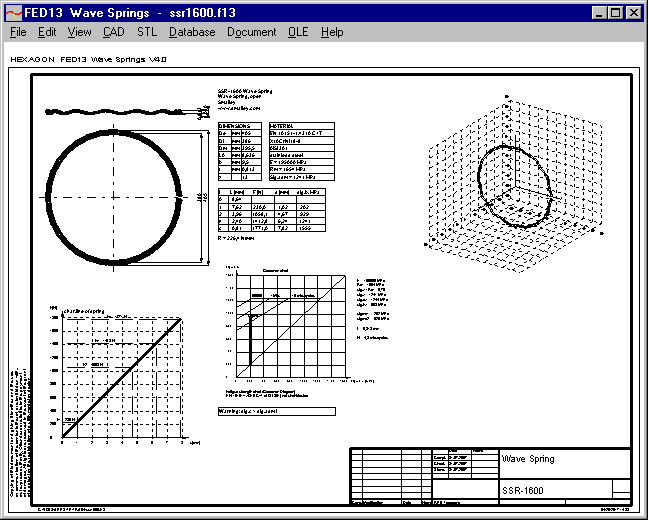
FED13 Quick4 View
Quick4 View includes wave spring data, drawings and diagrams altogether in an A3 drawing frame.
FED13 New Price
New price of FED13 (individual license) is 228 EUR (instead of 185).
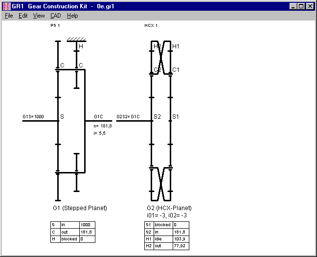
GR1: New gear elements "Stepped Planet" and "HCX Planetary Pair"
By means of our GR1 gear construction kit software you can now also assemble stepped planetary gears and "HCX" planetary gear pairs with crosswise connected carriers and hollow gears.

HCX planetary pair has, similar than Simpson or Ravigneux set, one or two input shafts, one output shaft and one idle shaft. Stepped planetary gears compared with simple planetary gears are used for larger transmission ratio.
ZAR4: Noncircular Gears with Mounting Mark
To avoid error in assembly, gears are now marked by an arrow.
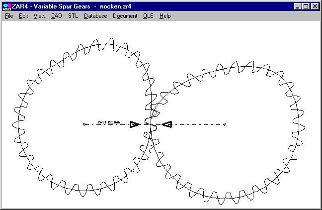
And a new demo version of ZAR4 was made with the possibility to produce noncircular gears on 3D printers.
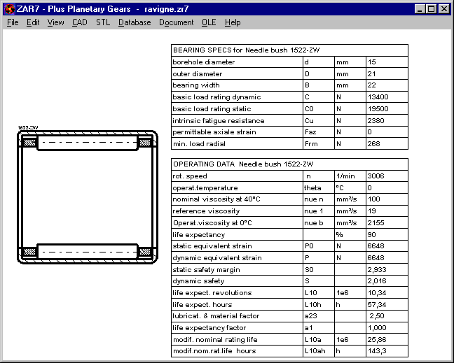
ZAR5, ZAR7, ZAR8: Roller Bearing Drawing
Same as known from LG1 and WL1+, drawing of roller bearing together withwith bearing data table can be shown and printed in the planetary gear software now. Thanks for the suggestion to Mr. Schulze of BS Antriebstechnik.
ZAR1+: Calculation to DIN 3390 Part 41
Apparently some users always calculate gear strength according to DIN 3990 part 41 because this is the most convenient way with only few input data. However, DIN 3990 part 41 is valid only for automotive gears of case hardening steel, surface hardened or carbonitrided, and for gear quality 5 to 7 according to DIN 3961 or 4 till 6 according to ISO 1328. New error message "DIN 3990-41!" appears now if one or more of these criteria are not fulfilled.
WN2+, WN4, WN5, WN10, WNXE: Plot direction
In a drawing it makes no difference in which direction lines, arcs and circles are drawn. Our DXF Manager software can be used in animation mode to show sequence and direction of DXF drawing elements. After each teeth there was a jump because drawing sense changed. This was unified now. If you convert tooth profile into a CNC track for wire eroding etc., track now runs without jump.
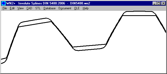
WN2,WN4,WN10,WNXE: Face width dimension in production drawings
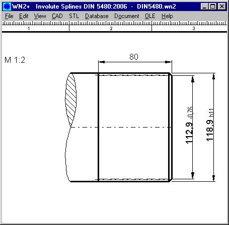
Length of toothing is dimensioned now in production drawing of involute spline software.
FED4, FED9, FED10, FED14, FED15, FED16: SWP-A and SWP-B added

SWP-A and SWP-B wire according to JIS has been added in the material database.
SR1+ Sealing Area at Eccentric Load
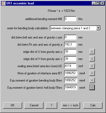
Button "<" at "AD" now calculates sealing area from minimum outside diameter and maximum bore diameter of both of the clamping plates that have been selected above. Thanks to Mr. Lederer of Vossloh Locomotives for the improvement suggestion.
Tip: Reduce file size of STL files
STL files of springs are very large because circles are drawn as polygons. Both, wire diameter as well as coil diameter. Resolution of coils can be configured at "Edit\Calculation Method", default is 2 deg. Resolution of wire diameter can be configured at "File\Settings\CAD". Not in degrees here, but in millimeters. Default is 0.1mm. STL file of a compression spring with d = 3 mm and 5 coils was by default 10 MB. By increase of angle to 10 deg and resolution to 0.5 mm, file size was reduced from 10 MB to 0.5 MB.
FAQ: What means Fn' in Load-deflection diagram of FED1+ ?
Fn' is the load with shear stress taun' = tauz (permissible). Fn´ is displayed and printed only for springs with shear stress at block length higher than permissible shear stress (tauc > tauz).