

ZAR5: Power shearing (driving shaft + control shaft) as option
Sun gear, planet carrier and ring gear are connected with driving shaft (input), driven shaft (output) and control shaft (control). If control shaft is locked, power flows from input shaft to output shaft. If input shaft and control shaft are connected (for direct transmission i=1) or input shaft and control shaft are driven by the same motor with different speed (i.e. Lepelletier planet gear set), power will be shared between input shaft and control shaft (P_input + P_control = P), check "power sharing Input+Control". If not checked, full power always flows to input shaft, and control shaft requires external power (or braking power, if negative). Ratio of power sharing depends on gear ratio.

If control shaft is locked (n=0), control power (P control ) is 0. Power sharing checked or not does not influence output power and torque in this case.
ZAR5: Wolf chart with torque, speed and power
Rotational speed and power at sun shaft (S), carrier (C) and hollow wheel (H) have been added to Wolf diagrams, and also planet gear transmission ratio i0 (zH/zS) and pitch power Pw.

Wolf chart for planet gear with connected input shaft and control shaft (i=1).
ZAR5 : Strength calculation for zero speed planet gear
If input shaft and control shaft are connected (i=1, n control = n input). Planet gear speed relative to carrier is 0 (npc=0). Fatigue strength of gear wheels could not be calculated in this case. Since release 10.0, ZAR5 calculates SH and SF as static safety coefficients from torque.
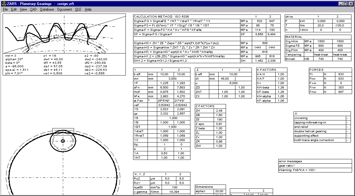
ZAR5: Screen graphic of gear pairs dimensions and strength calculation

Same as in ZAR1+, you can now get screen with nom/min/max dimensions and strength calculation for gear pairs sun-planet and planet-ring gear.
ZAR1+: Strength calculation for zero speed gear

In earlier versions, ZAR1+ calculated fatigue strength only if speed > 0 and power > 0. Since release 25.0, ZAR1+ calculates static safety SH and SF for the given torque even if speed n=0.
ZAR1+: Printout with load spectrum and multistage gear
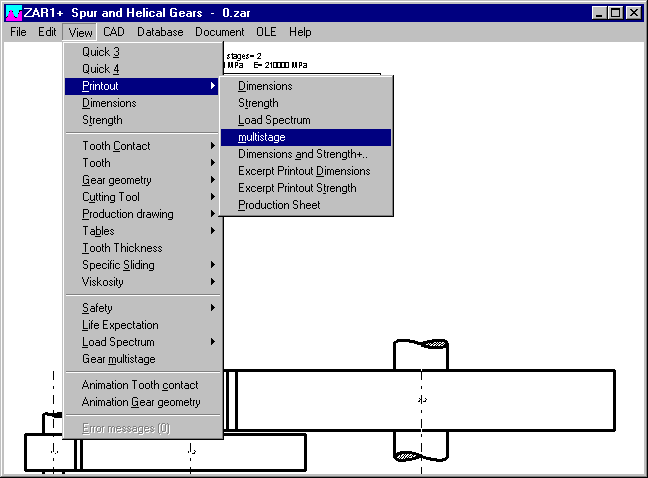
Results of load spectrum calculation and multistage gear calculation can be printed separate now at "View->Printout"
ZAR1+, ZAR5: Edit Dimensions
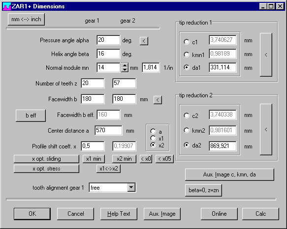
Buttons x1min and x2min or xSmin and xPmin set minimum profile shift coefficient only if larger than 0. Else, x will be set 0.
ZAR1+: Input profile shift and center distance
At input of gear pair dimensions you can select which one of the three values center distance, profile shift coefficient x1 or x2 should be calculated. Input has been optimized, selected value is calculated and shown now immediately after input of a, x1 or x2.
ZAR1W: CAD Tooth profile input window
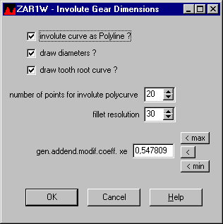
As known from the involute spline programs, before generating the gear profile at "CAD->Tooth Profile Gear" you now get an input window with settings for profile shift coefficient or flank clearance, resolution of involute and tooth root curve, and drawing parameters.
FED1+,2+,3+,4, WN1, ZAR3+: Online Input with green and yellow fields
"Online Input" is used for input windows with recalculated and updated results after each input step. Input fields are marked yellow now, if this field is a calculated value and input changes other input fields. So you are warned that input in a yellow field may change previous input data.

A green input field means that the entered value is only approximate, it may be rounded or changed. This is the case for extension springs and torsion springs, where calculated number of coils must be rounded to loop position or leg angle, and the rest must be compensated by modified coil diameter.

Recalculation of cylindrical press fits with WN1 has many yellow fields: Input of ISO tolerances calculates tolerances A and then interference U of shaft and hub fit. Modification of tolerances A clears ISO tolerance. And modification of interference U clears all, tolerances A and ISO tolerances.
Spring material FD, TD, VD according to EN 10270-2
Old DIN 17223 defined material types FD for static and VD for dynamic load.
New EN standard defines FD for static load, TD for mean fatigue strength and VD for "difficult dynamic load". TD material types were not included in the fedwst material database as separate material until now. If your spring material database includes "TD" as second name in "Name3" or "Name4" of "VD" material, please clear "TD" at "Database->fedwst.dbf". Tensile strength and permissible shear stress of TD and VD is equal, but fatigue strength of TD is lower than VD.
EN 13906-1:2013 includes Goodman diagrams for TD (= FD) and VD. If these should be applied for FDC, TDC and VDC only, or also for FDCrV, FDSiCr, FDSiCrV, TDCrV, TDSiCr, TDSiCrV and VDCrV, VDSiCr and VDSiCrV, is not articulated. Fatigue strength data of VDSiCr and VDCrV used in fedwst.dbf is substantially higher than for VDC and originate from Bosch RDZ charts.
TDC, TDCrV, TDSiCr and TDSiCrV have been added in FEDWST.DBF now as separate materials. TDC with fatigue strength values of FDC and tensile strength parameters of VDC. No Goodman diagram is available for TDCrV, TDSiCr and TDSiCrV, but tensile strength is equal with VDCrV, VDSiCr and VDSiCrV.

FED1+, 2+, 3+,5,6,7, 8: Temperature-dependant E modulus and G modulus
According to latest EN 13906-1 of 2013, spring wire to EN 10270-3 and to EN 12166 (bronze, copper alloy) are calculated with another temperature coefficient. New formula is used in our spring calculation software now.
G = G20 * (1 - r * (t –20)) with t = temperature in °C
r = 0,25e-3 for spring steel wire to EN 10270-1, EN 10270-2 and EN 10089
r = 0,40e-3 for spring steel wire to EN 10270-3
r = 0,40e-3 for spring wire to EN 12166
In earlier releases of EN 13906, a diagram instead of a formula was used to get temperature dependency. Converted into coefficient r, diagram values correspond to r= 1/3600 = 0,28 e-3.
Because formula was modified in the programs, you will get now slightly differing results when you load earlier calculations with operating temperature other than 20°C. If you open files in FED1+, number of coils is modified, spring loads remain unchanged. In FED2+, coil diameter may be modified, in FED3+ number of coils and delta0, in FED5, FED6 and FED7 the spring loads.
FED1+, 5, 6, 7: Reduced spring mass by grinding of spring ends
Grinded material of the end coils had not been considered in spring mass calculation, this was improved now.
FED5, FED6, FED7: Pitch height considered for calculation of wire length
Same as already in FED1+, also FED5, FED6 and FED7 calculate wire length with consideration of spring height. In earlier versions, wire length was calculated simply as pi*D*nt.
FED1+: Pitch m and swelling of the outside diameter deltaDe under load
In EN 13906-1:2013, calculation of pitch "m" for calculation of deltaDe was corrected (19). In FED1+ and FED6, coil pitch "m" ("P0" in FED1+) since years is calculated to the new formula: m = (L0-Lc)/n+d (see info 121). This is equal with the new formula in EN: m = (sc + n*d)/n. More simply it should be: m = sc/n + d. However, this formula is valid also for compression springs with raw spring ends. The other formula "m=(sc+(n+1.5)*d)/n" in EN 13906 is superfluous and wrong, cause difference for raw end coils is already included in block deflection sc.
FED1+, FED5, FED6: Dimensions of mandrel and bore separate

Fields for mandrel and bore have been separated in the production drawing input window to avoid overlap when define spring led by both, mandrel and bore.
FED3+ Legs bent-up, axial

Legs can be tangential or bent-up external, internal, or axial (new).
FED5: Concentric end coils
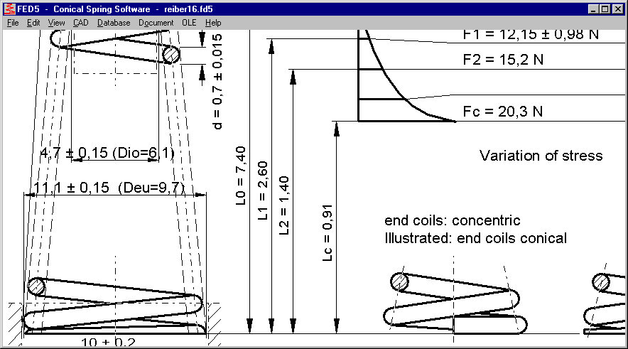
If concentric end coils defined, FED5 production drawing includes dimensions of minimum inside diameter and maximum outside diameter of the end coils instead of coil diameters (coil diameters Dio and Deu in brackets). Production drawing always illustrates conical end coils.
SR1+: Calculate deformation cone of TTJ with TBJ calculation method
VDI 2230 differs calculation of deformation cone between TTJ and TBJ. In figure 9, deformation cones are illustrated (a), but VDI 2230 uses one deformation cone followed by a sleeve "to simplify the calculation". This calculation method is not applicable for a bolted joint of several clamping plates with more than one deformation cone. But even for simple calculations, this simplified calculation method seems to be incorrect. Example: B2 of VDI 2230

Supposed a tapped thread joint (TTJ) instead of through-bolt joint (TBJ). Then calculate cone angle tan(phiE)=0.348+0.013*ln(ßL)+0.193*ln(y)= 0.647 (phi=32.8°, larger than phiD of TBJ!)
DA,Gr = dw+2*lk*tan(phi) = 100 mm (larger than TBJ!)
Comparing the deformation bodies of TTJ joint and equivalent TBJ joint shows that there must be something wrong: The TTJ deformation body is only one huge cone, because "DA,Gr" nor "de" will be reached.
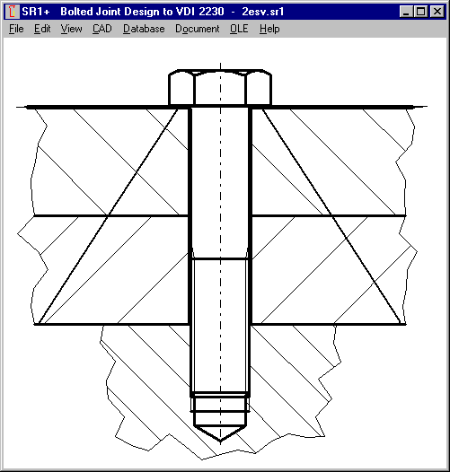
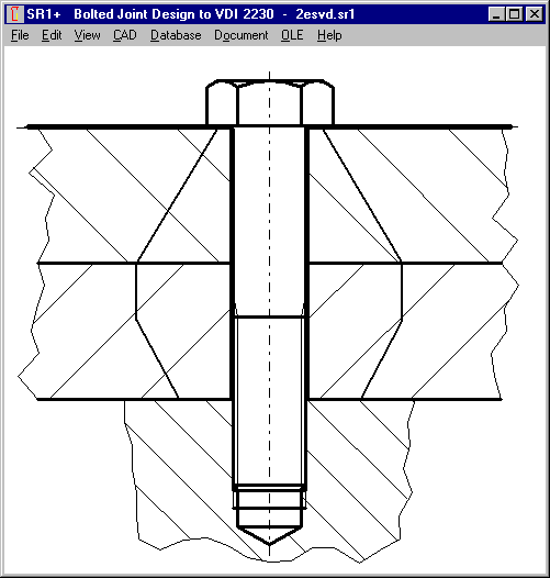
In SR1+ you can now set the option "TTJ -> TBJ (phiD, dwNut)" to calculate the deformation body of the TTJ in the same way as for TBJ. SR1+ calculates bearing diameter of the female thread according to figure 9 of VDI 2230-1:2015 (dw= d + 2*tan(phiD)*mgeo with mgeo = screw-in depth of bolt in female thread, possibly less one thread pitch).
Because cone angle phi depends on bearing diameter dw and vice versa, dw and phiD are calculated iterative.
SR1+: Calculate pressure from deformation cone cross-section

In earlier versions of SR1, pressure F/A between clamping plates was calculated with virtual external diameters according to VDI 2230:1986. At "pmax" you now can calculate pressure from section area of the deformation cones. If TTJ, better set "TTJ -> TBJ (phiD, dwnut)", else you may get too large cross-section area resulting in too low pressure. In most cases, flank pressure safety margin remains the same, because maximum value applies between bolt head or washer and first clamping plate, or between nut and last clamping plate.
SR1+: Non-standard sizes added for hexagon head bolts
Sizes M45, M52, M60, M68 and M160 added in the database (according to DIN 931).
SR1+: Safety not shown if S>1000
At Quick3 View, Quick4 View, and table drawing, safety margins are listed only if less than 1000.
WN8: ISO tolerance for self-defined splines
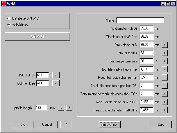
For self-defined splines you can now input ISO tolerance for tooth tip diameter of internal and external spline. If nothing entered, diameters are calculated without tolerance. If you select profile from DIN 5481 database, ISO tolerance A11 will be set for internal spline and a11 for external spline. In self-defined splines, root fillet radius can be set 0 now. In earlier versions, maximum fillet radius was calculated in this case.
Involute spline package
For calculation of involute splines to different standards DIN 5480, ANSI B92.1, ISO 4156, DIN 5482 and self-defined involute splined joints, we offer now a bundle with WN2+, WN4, WN5, WN10 and WNXE for a price of 1200 Euro.