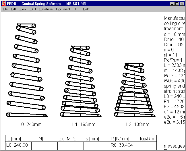

FED5 – Conical spring drawings with end coils

Conical spring is drawn with end coils now in section drawing, in "Quick3" and "Quick4" View, and in animation.
FED1+,2+,5,6,7: Warning "tau2 > tauz min !"
A new warning "tau2 > tau z min !" refers to minimum tensile strength from table fedrmmin.dbf, if material was selected from database, and if a table with tensile strength tolerances is available for the selected material. Tensile strength data in fedrmmin.dbf and fedrmmmax.dbf refer to wire as delivered. If tensile strength of the finished spring higher than that of the raw wire (i.e. by age hardening of stainless steel) you can ignore the warning. If you configure "Hide warnings" or uncheck "display Rm min/max, taumin/max" the warning is disabled.
FED6, FED7: Animation with load-deflection diagram
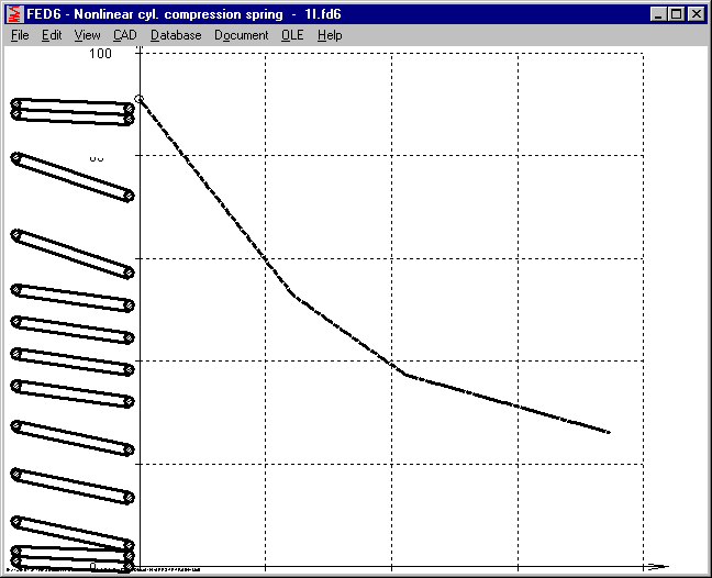
Load-deflection diagram is drawn now side-by-side with the animated spring, and a point moves along the load-deflection curve due to deflection of the spring.

FED1+, FED3+, FED5, FED6 - Input mandrel diameter
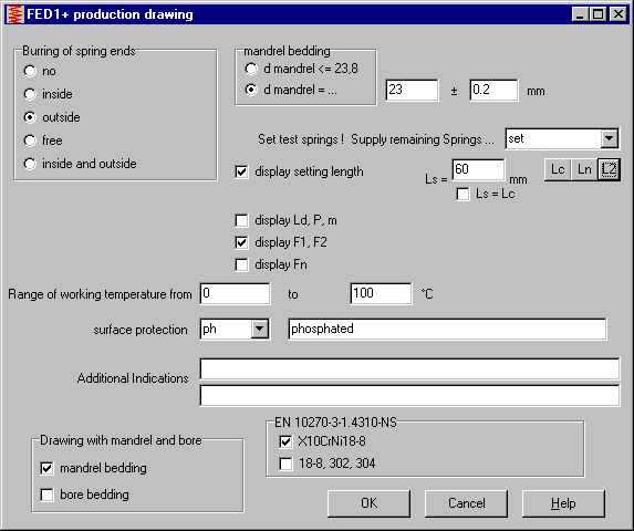
Maximum usable mandrel diameter for compression springs or torsion springs is calculated and displayed in the production drawing with mandrel diameter "<= x.x". As alternative, you can now input mandrel diameter with +/- tolerance. If entered diameter plus tolerance is larger than calculated maximum, you get an error message.
FED1+, FED5, FED6: taukn and taukc

If dynamic loaded, shear stress is multiplied by dynamic stress correction coefficient k. Dynamic zone lies between spring deflection s1 and s2 with stresses tauk1 and tauk2. Block stress tauc is static. Thus tauk2 can be higher than tauc. Theoretical dynamic stress at block (taukc) and at usable length (taukn) is listed in brackets now with load-deflection diagrams and stress-deflection diagram.
FED1+, FED3+, FED6: 3D helical center line for rectangular and elliptic wire
3D centerline can be drawn for all wire types now. For ground end coils, 3D line begins near z=0, and for raw end coils near z=d/2. Height of the centerline of an unloaded spring can be calculated from unloaded spring length L0 and block length Lc: L0center = L0-Lc+nt*dmax
If you want a drawing with nominal dimensions without tolerances, set wire tolerance to 0 at "Edit->Material", then check "Lc=(nt+1)*dmax" if raw end coils or "Lc=nt*dmax" if ground end coils at "Edit->Production".
FED4: F-L Diagram

Spring length instead of deflection is drawn on the x axis of the new F-L diagram in FED4.
FED4: Animation
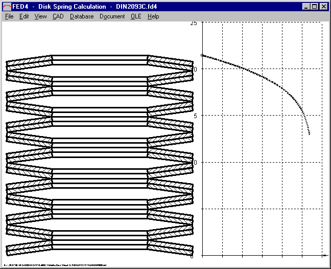
Animation simulates deflection of the disk springs on screen. You can define start length, end length, number of steps and pause. A moving point on the load-deflection diagram shows present load of the spring package.
WN9: CAD profile drawing min/mean/max

Profile of straight splined shaft and splined hub has been drawn with mean tolerance until now. In the new version of WN9 you can enter dimension or click min/mean/max buttons to set dimension with desired tolerance for spline profile drawings.


SR1 - Small Thread Size
Thread sizes M1.6, M2 and M2.5 for hexagon socket head screws according to EN ISO 4762 have been added to the database.
WN1, ZAR1+, ZAR2, ZAR5, ZAR6 – Production Drawing in standardized scale
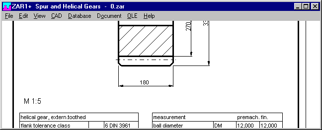
Configurable border width of ISO 7200 drawings with coordinates and mm scale

According to ISO 5457, border width to drawing area is 10 mm (bottom, top, right) and 20 mm left. Old DIN 6771 defined 5 mm and 15 mm left. This reduces drawing area by 10 mm in height and width. Until now, production drawings (A4) and Quick4 View (A3) were drawn with 5 mm border. Now you can configure ISO 7200 drawing with 5 mm or 10 mm border. If 10 mm border configured, you can fill the border with coordinates A,B,C,D – 1,2,3,4.. and/or a millimeter scale.
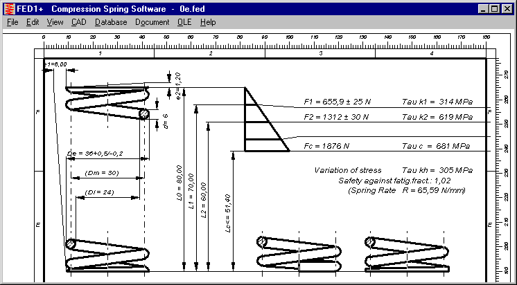
However, the 10 mm border can not be used with each production drawing until now, because i.e. the A4 table drawings of the springs require the complete drawing area.
But "Quick4" drawings and "Quick3 Production Drawing" in each program had been checked and modified to fit in the ISO 7200 drawing with 10 mm border.
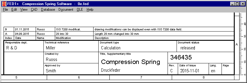
ISO 7200 title block with modification index
According to ISO 7200, drawing modifications are no longer described. Only the modification index is listed as letter A,B,C. Nevertheless, you can now configure to list the modifications directly above the title block
Extend Title Block by self-defined drawing elements
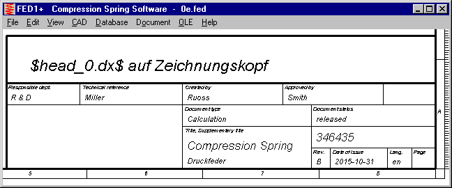
If you want to extend the standard title block by self-defined standard specifications, symbols and drawing elements, you can create a title block extension drawing and save it as DXF file. Insertion point is the left upper corner of the configured title block (ISO 7200 or DIN 6771). Create a DXF drawing and convert into a DX$ file, copy into temporary directory and set read-only file attribute. With different file names the drawing extensions are used with A4 drawing, A3 drawing (Quick4), or with each production drawing:
$HEAD_0.DX$: drawing inserted above title block.
$HEAD_4.DX$: drawing inserted above title block, A4 production drawing only.
$HEAD_3.DX$: drawing inserted above title block, A3 drawing (Quick4) only.
Extend drawing by self-defined drawing elements
You also can insert self-defined drawings at coordinate origin (0/0) of the generated drawing. Convert your DXF drawing into DX$, save in temp directory and set R/O attribute as described previous.
$INSERT_0.DX$: drawing inserted in A3 or A4 production drawing
$INSERT_3.DX$: drawing inserted in A3 production drawing (Quick4)
$INSERT_4.DX$: drawing inserted in A4 production drawing
At "File->Settings->Drawing" you have to configure that self-defined drawing elements must be used.
Open manual

Each program got a new menu item "Help->Manual" to run the electronic manual. Manual is delivered as PDF files and one index HTM file. Your computer must have installed PDF viewer and HTML Browser (no internet connection required) to run the e-Manual. Folder with manual pdf and htm files can be configured at "File->Settings->External". Default setting is program path.

FNAME Tool for lowercase file names
Windows makes no difference between uppercase and lowercase characters in file names, but Unix does. If you run software and e-manual on a Unix server and get error messages "file not found" maybe could be the reason. File names must be lowercase. You can use our tool "FNAME" ("FNAME *.*") to convert file names in lowercase characters. Customers can download the tool at www.hexagon.de/history/tools.
Installation with or without Setup.exe
Under Windows 10, waiting period at installation with setup.exe can be up to one minute, no idea why. Because the blue annulus is rotating and nothing else seems to happen, it looks like setup.exe hangs. But you have to wait until setup window closes. As alternative, you can install programs without setup.exe. Just unzip or copy the files in a new folder. Then create a shortcut on the desktop to run the program.
In earlier versions, setup.exe also linked HEXAGON program with file extension of the calculation files, but since Windows Vista HEXAGON Setup.exe fails with registering file extensions. Link file extension with calculation program is useful if you want to start the calculation program by a double click into the calculation file.
Tip: Link file extension with program
Example: Make Windows 7 to open .sr1 files with SR1+ (wsr1.exe)
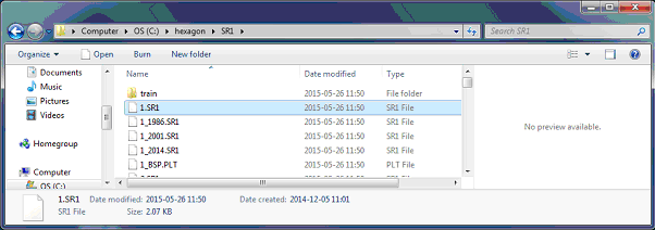
Use Windows Explorer and double click file (1.SR1)
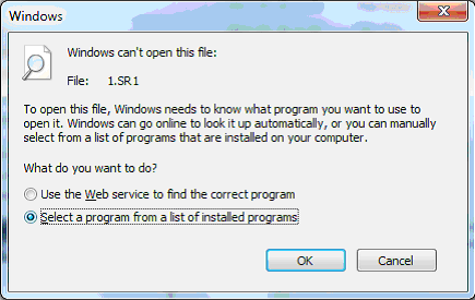
"Select a program from a list of installed programs".
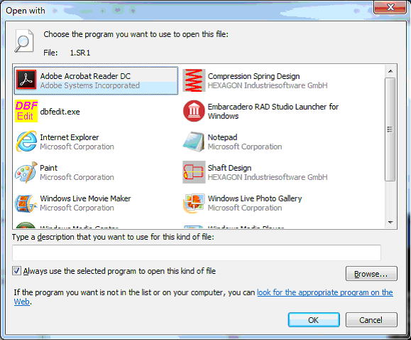
"Browse..."
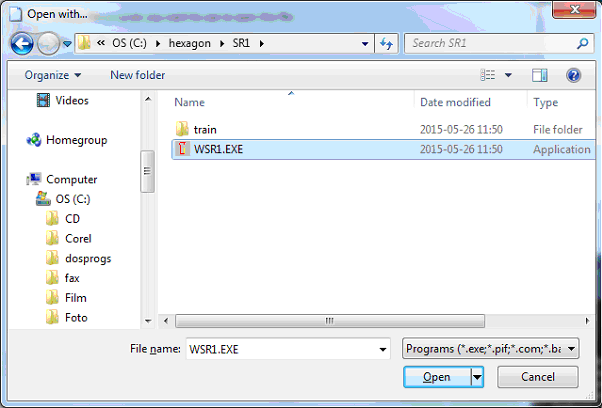
Select program (c:\hexagon\sr1\wsr1.exe), then "Open"
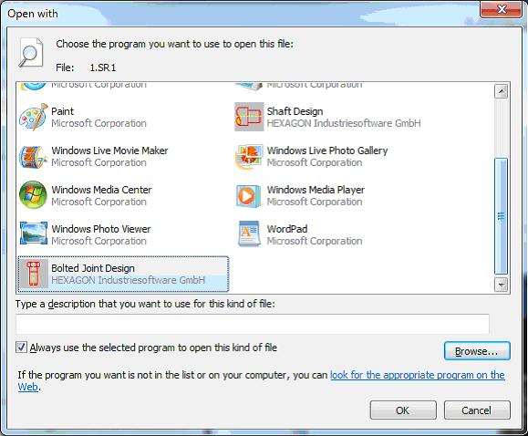
"OK".
WSR1.EXE opens 1.SR1 file. Done!