
SR1 – "Calc" Buttons

A new "Calc" button has been added into the input windows for friction, load, tightening, eccentric, flange and calculation method. Click "Calc" button to calculate the bolted joint and display results in the background graphic. "Calc" buttons help to get a desired value iterative, or to check the effect of variable input values.
DI1, FED1+, 2+, 3+, 4, 5, 8, 9, 11, 12, 13, 14,15, GEO3, LG1, LG2, SR1, WN1, 2, 3, 4, 5, 6, 7, 8, WN9, 10, 11, WST1, ZAR1+, 2, 3+, 4, 5, 6, ZARXP, ZAR1W, ZM1: Calc Buttons

Almost all of our programs got new "Calc" buttons in the input windows. "Calc" button causes recalculation of the machine element and shows results in the background window. "Calc" button is useful if you want to see the effect of a varied input value on the result. On earlier versions, you had to close and re-open the input window for these calculations.
SR1 – Quick4 View

New Quick4 View includes all the data known from Quick3 view, and additionally load-extension diagram, M-alpha diagram, FM-alpha diagram, FM-MA diagram, and radial distribution of pressure if eccentric load. All together on one screen in an A3 drawing frame. Without zoom, text on the computer screen is readable in highest resolution only.
SR1 – Material database for clamping plates and nuts
Selected material is identified by record number. Therefore, record number must not change. If you want to delete materials, just use "-" button to mark as deleted. Marked records are no longer listed as material to be selected. Do not use "Pack" function for physical erase of the records.
If you extend databases with self-defined materials, you have the problem to synchronize databases if you later want to integrate updated databases from HEXAGON. Another difficulty may be, that sr1 files are no longer exchangeable with other SR1 users who work with the original dbf files. I suggest that you send us your desire for database extensions, and we extend the databases with your data.
For material of clamping plates and nut, you meanwhile can choose between 3 databases: pressung.dbf with all data, mat_p_1.dbf with material data to VDI 2230:2003, and mat_p_2.dbf with materials according to VDI2230:2014. The "mat_p_1.dbf" is out of date and will no longer be updated, so this one can be used to be extended with your own internal materials.
Since Version 20.2, clamping plate material data of the database are compared with data from sr1 file and you get a message if data are not equal. This means that database had been changed. If only material name has been changed, or modified data are ok, just re-save sr1 file and the message disappears. If the messages are tiresome, as at "File->Open (Table)", you can configure help level 0 to suppress the messages.
SR1 – Flat-headed screw according to ISO 7380

Flat-headed screws according to DIN EN ISO 7380 have been added to hexagon socket head bolt database. Bolt head radius is equal than head height for this bolt type.
SR1 – Input clamping plate material

Since release 17.3 you have the option to input material data directly instead of selecting material from databases. Unfortunately, the entered data had been overwritten if in the material database was found a material with equal name. This has been corrected now, so that the self-defined data of pressure limit, modulus of elasticity, yield point and thermal expansion coefficient always are loaded correctly.
SR1 – nut thread with counterbore or necked-down bolt with incomplete thread engagement
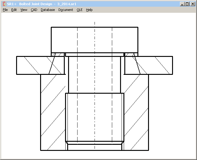
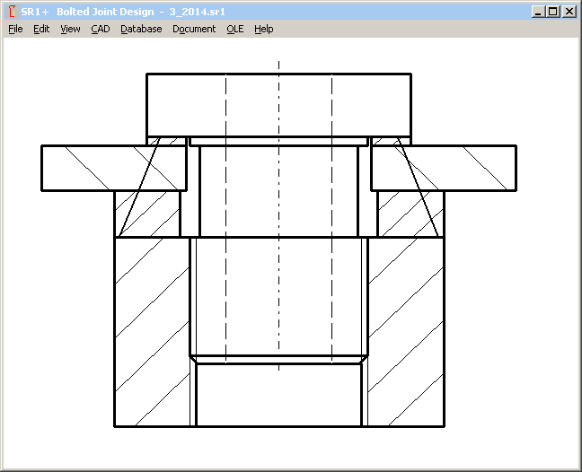
A new error message "lG3 bolt < 0" indicates that non-bearing part of bolt thread was calculated smaller than 0, because either a necked-down bolt is incompletely engaged in the nut thread, or a part of the nut thread is countersunk. In this case, the clamped part of the nut has to be defined as clamping plate, and nut height reduced by the countersunk height. Application example 3 of VDI 2230 shows such case: elastic resilience is increased by necked-down bolt and countersunk of the nut thread in the crank shaft. The clamped part of the nut thread (crank shaft ) must be defined as additional clamping plate.
TOL1, TOL2: Reject Rate added in Gaussian Graphic
Input of sigma coefficient defines reject rate of tolerances. Reject rate in % (per cent) and ppm (parts per million) for the calculated closing dimension tolerance has been added in the Gaussian curve graphic.

FED1+ 2+ 3+ 5 6 7 – Additional Relaxation Diagrams

New relaxation diagrams are Rx = f (tau/tauz, T, d) t with the coefficient tau/tauz (shear stress divided by permissible shear stress), and f (tau,T) with wire diameter of the calculated spring and shear stress on the x-axis, and f (T,tau) with temperature on the x axis.
FED1+ 2+ 3+ 5 6 7 – Relaxation curves for various temperatures
New relaxation curves with wire diameter of the calculated spring and shear stress on the x axis are drawn for this temperatures:
- temperature limit T1 (min) of database fedwstr.dbf
- temperature limit T2 (max) of database fedwstr.dbf
- operating temperature from "Edit->Application"
- max. range of working temperature from Edit->Production Drawing
If operating temperature or max working temperature is equal with T1 or T2, only one curve will be drawn.

FED1+ 2+ 3+ 5 6 7 – Relaxation curves as function of temperature
Another new diagram indicates relaxation with temperature on the x axis and curves for shear stress tau1, tau2 and tauz (permissible) of the calculated spring.

FED1+ 2+ 3+ 5 6 7 – Relaxation for small wire diameter and low temperature
Relaxation is calculated from the parameters in fedwstr.dbf database: wire diameter D1 (min) and D2 (max), temperature limits T1 (min) and T2 (max). Relaxation for other values is calculated by interpolation. If temperature is below T1, relaxation is calculated with T1.
If wire diameter is smaller than D1, relaxation will be calculated with D1. In earlier versions, relaxation of a smaller wire diameter was logarithmic interpolated. But the calculated relaxation was too low in this case (even smaller than 0 for a wire diameter smaller than 0.5 mm).
FED1+ 2+ 3+ 5 6 7 – New records added in relaxation database
Relaxation data of EN13906 are used now following materials, too:
18: 1.4310: -> 26 (11R51), 27 (12R10), 42 (302/304), 59 (Loniflex)
19: 1.4568: -> 28 (9R10), 43 (17-7PH), 86 (GARBA177Supreme), 87 (GARBA177PH)
56: 1.4462 Springflex: -> 78 (1-4462-NS)
57: 1.4462 Springflex-SH: -> 79 (1-4462-HS)
8: -> 41 (CrSi)
10: VD-SiCr : modified acc.to Bosch (lower relaxation for higher stress and temperature)
10: VD-SiCr: -> 49 (Oteva70SC shaved.), 50 (Oteva70 not shaved)
FD CrV: 40 (CrV)
FED1+ 2+ 3+ 5 6 7 – Relaxation data
Relaxation database fedwstr.dbf was extended by info columns "SOURCE" and "PRE_SET". "Source" is the source of the relaxation data (EN 13906). "Pre_set" informs about presetting of the spring. Theoretically, relaxation diagrams should be based on non-preset springs. But practically, provided relaxation diagrams stand for springs "preset at room temperature" (EN 13906), or "cold preset", "optimum preset" (Bosch) or "hot preset" (Oteva).
If the spring will be cold preset for 10 hours, relaxation is 75% according to the Rx=f(t) diagram, thus the remaining relaxation is 25%. This means that the relaxation curves of a preset (10 hours) spring should be 4 times lower compared with an untreated spring.
FED1+ Dimensioning Material -> Relaxation
This new function is useful if you want to compare relaxation of different materials. Select material in the input window, and check relaxation diagram in the background graphic.
FED1+ Load-deflection curve with tolerance zone: relaxation curve added
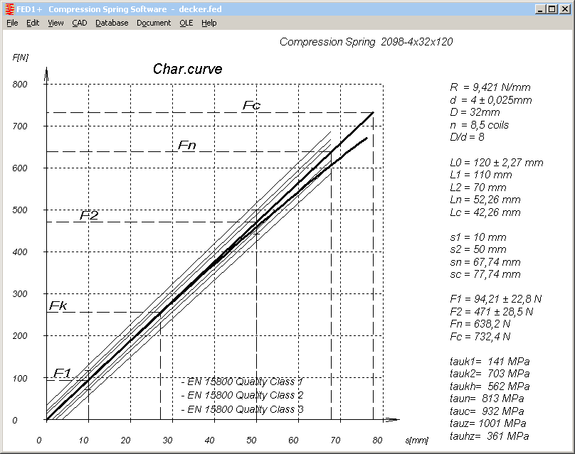
Relaxation curve has been added in the load-extension diagram with tolerance zones. This is the spring load less relaxation after 48 hours.
FED3+ Radial load warnings
If legs are held over lever arm R, FED3+ calculates forces F1=T1/R and F2=T2/R. These loads induce the torque T=F*R, but also a radial load on the spring body. If spring is used against coiling direction, coils may lift off from the spring body and thus reduce spring torque. FED3+ now calculates radial deflection sQ2 at spring position 2 from spring load F2=FQ. FED3+ generates a warning "FQ! sQ=..." if sQ is higher than the gap between inner coil diameter and mandrel diameter. And a further warning "FQ! MQ=..." if friction torque between spring body and mandrel is more than 5% of spring torque T2. With MQ=F2 * µr * Di/2, assumed friction coefficient µr=0.1.
FED5 with EDI Export/Import
FED5 got EDI interface for data import/export from/to other programs (as in FED1+ and ZAR1+). Application example: FESTO uses the EDI interface for transfer of dimensions and technology data into the CAD system.
FED9 – Pre-dimension improved
In some cases the calculation was interrupted due to an error "al.c<0" (negative block angle). Now, calculation continues until a suitable spiral spring was found.
FED14 - French version
New Software FED14 for helical wave spring is also available in a French version now.
FED4 - Italian version
Disk spring software FED4 is also available in an Italian version now.
ZAR1+ Production drawing without nominal dimensions
To avoid confusion at production, nominal values of dimensions over pins/balls and span width were removed at production drawing, listed only in Quick3 and Quick4 View. The dimensions "nom" or "theor" are normally even larger than the "max" values, because upper and lower tolerances Asne and Asni are both negative.

ZARXP – Quick View
A new Quick View with tooth profile and table with dimensions on one screen has been added in ZARXP involute profile software.

ZAR1+ Tooth profile drawing without gap
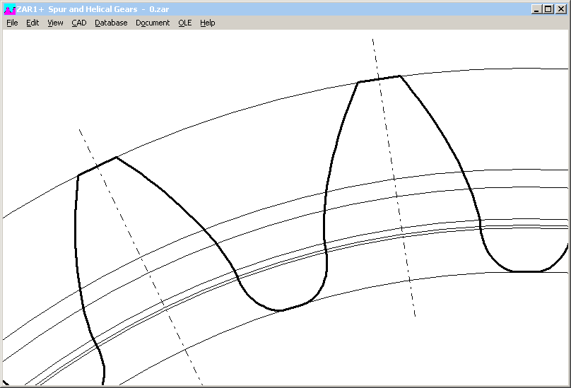
Because of different curves for involute and tooth fillet trochoide remained a small gap in the transition of the fillet into involute. Now both curves are connected to avoid the gap.
ZAR1+, ZAR2, ZAR5, ZAR6: Input power, speed and interval time of load spectrum
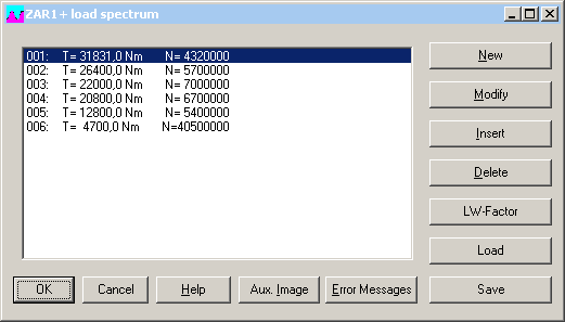
Instead input of torque and number of load cycles, you now have the option to enter speed, torque, power, and time interval for each load step as well.

WNXE – New software for involute splines
With WN2, WN4, WN5 and WN10 we already provide software for involute splines according to DIN 5480, ANSI B92.1, ISO 4156, and DIN 5482. Our new software WNXE enables you to calculate dimensions of any involute spline very quickly. WNXE is the ZARXP for involute splines. You can measure over pin dimension, calculate given splined shaft or splined hub, design counterpart, and create true-scale profile as drawing.

You can input dimensions of internal and external spline and calculate clearance and backlash, or input external spline and clearance and calculate internal spline, or input internal spline and clearance and calculate external spline. Even dimensions of exotic designs (i.e. JIS splines with 20° pressure angle and large profile shift) can be calculated easy and quickly.
In WNXE, you enter dimensions directly, same as in ZARXP. No nominal dimensions, no tolerances. If tolerances should be considered, you have to do two calculations: one with min tolerances for minimum clearance, and one with maximum tolerances for maximum clearance. And maybe one for average tolerances to create the true-scale profile drawing. Profile drawing can be generated as DXF or IGES file to be used for CAD, gear cutting, wire eroding, 3D plotting..
Comparison of WNXE, WN2+ and ZARXP
|
WNXE |
WN2+ |
ZARXP |
|
|
Calculate dimensions and draw profile |
X |
X |
X |
|
Calculate load bearing capacity (torque etc.) |
- |
X |
- |
|
Tolerances and tolerance zones |
- |
X |
- |
|
Calculate gear pair of internal spline and external spline |
X |
X |
- |
|
Design counterpart from clearance |
X |
- |
- |
|
Calculate profile shift from measured dimensions |
X |
(X) |
X |
|
Calculate tooth height factors from diameters |
X |
- |
X |
Configuration of temporary path with network versions

Temporary path is used to create and shift temporary files for database operations and for creating CAD files and screen graphic. Temporary directory should be individual, fast, and local.
- If several users use the same temporary directory, you may get data collisions and even program crashes.
- Low-speed access to the temporary directory decelerates screen graphic drawings as well as index and sort functions of databases.
- Configuring a network directory as temporary directory generates unnecessary network traffic.
Installation of HEXAGON Software on USB Disk
Individual license of HEXAGON Software can also be installed on USB disk. This enables you to have your software with you on your office computer, take with you on mobile notebook, and also use on your home computer. Key code are generated from hard disk data.