
25 Years HEXAGON GmbH
Info letter 150, with 6 info letters in one year, makes 25 years HEXAGON info letters - and 25 years ago, in April 1990, the HEXAGON Industriesoftware GmbH was founded. Since then, customers are informed every two months about HEXAGON Software news.
The first software, TOL1 for tolerance analysis, originated even 3 years before in 1987, provided by Fritz Ruoss engineering office. At that time, no Windows and no internet existed. The calculation programs ran under MS-DOS, system requirement was a IBM compatible personal computer with 512 kB RAM and floppy disk drive 5.25"/360 kB.
28 years later, more than 2500 customers with more than 10,000 licenses trust in calculations done by HEXAGON software.
With the 25th anniversary, we provide two new programs: FED14 for helical wave springs and FED15 for simple leaf springs.
FED14 - New Software for Helical Wave Springs

Helical wave springs are calculated like open wave washers with several turns. Crest of the waves must meet the crest of the next turn, therefore the number of waves per turn must always be x.5. Ideally, the crests of the waves should be welded together with the next turn waves to avoid the waves shifting under load, and crest of the waves slide in the valley of the next turn wave. To keep the distance between the crests relative high, number of waves per turn is only 2.5 or 3.5 or maximum 4.5. By friction and the effect as mentioned above, helical wave springs also appear a tolerance dependent, non-calculable hysteresis effect.
Spring load can be calculated from bending of the waves. Spring load caused by torsion of the helical spring flat is negligible small.
Advantage of helical wave springs compared with helical compression springs is a high load on a small volume. But as precision springs, helical wave springs are rather unsuitable.
For calculation, uncoiled helical wave spring can be calculated like a leaf spring with z bearings:
s = F * Lł / (16 * E * b * tł *N^4)
with L = pi * D * n
N = n * z
n = number of turns, z = number of waves per turn, t = flat thickness, b = flat width, E = E module
FED10 leaf spring software can be used to calculate one turn of a helical wave spring, in example a coil with 3.5 waves. Spring flat is bedded on 4 bearings. Radial forces are bedding loads of the next coil. Forces have to be distributed so that deflection is equal for all waves. Left is spring end, and on the right side a bending moment of the first wave of the next turn has to be introduced.

Curves of bending moment and bending stress by means of FED10

Maximum bending moment and bending stress is in the load introduction positions and in the bearing points, that are the crests of the waves.

FED14 - Helical Wave Spring
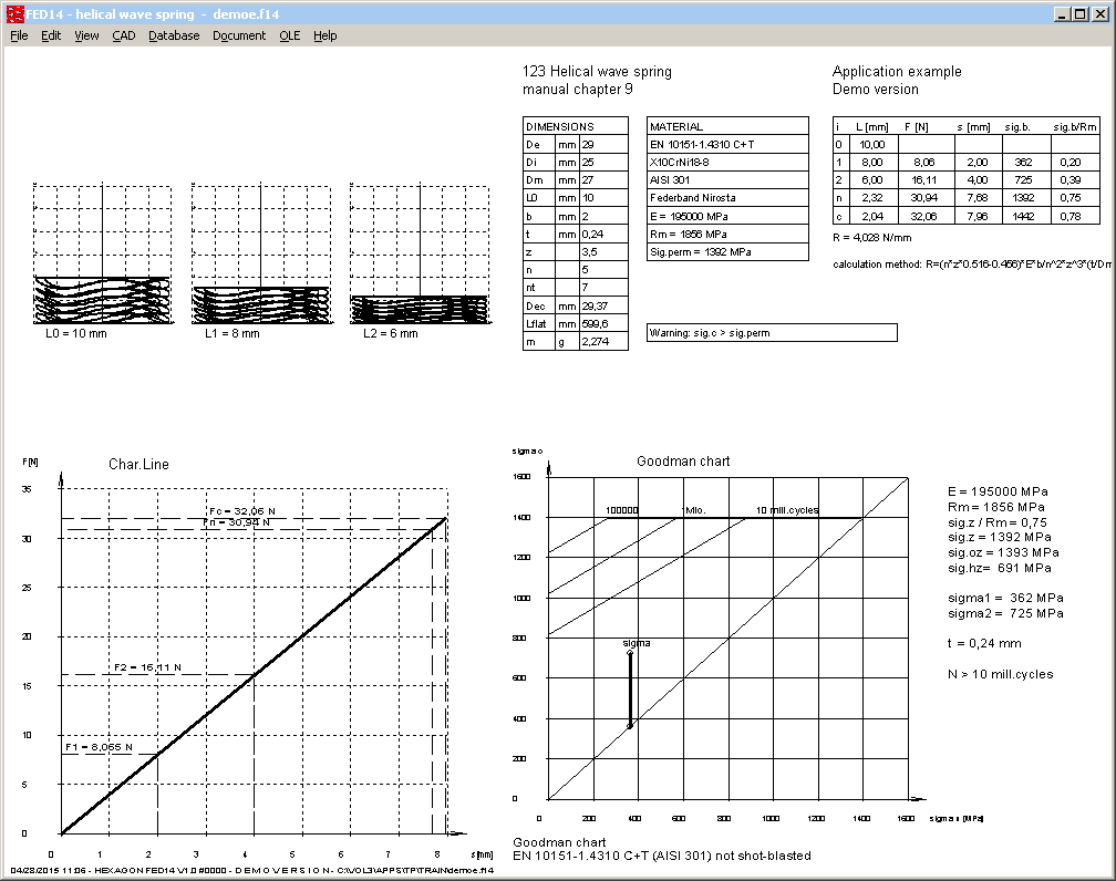
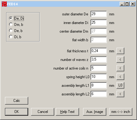
FED14 provides two methods of calculation: recalculation and pre-dimensioning. For recalculation, enter the dimensions and FED14 calculates loads and stress.
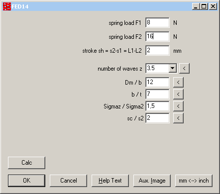
In pre-dimensioning, just input two spring loads and stroke, or only one spring load and deflection, and FED14 calculates dimensions. To vary results, you can edit number of waves, coil ratio, safety sigmaz/sigma2 or ratio of block deflection sc/s2.
FED15 new software for simple leaf springs
We already have another leaf spring software FED10 for complex leaf springs. FED10 calculates bending and stress in any position, and spring can be loaded with several radial and axial forces, path loads and bending moments.
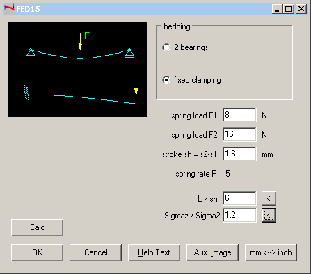
In FED15, you can calculate simple leaf springs with constant rectangular cross-section and only one radial load by few clicks.

In FED15, you can choose between "fixed clamping" and "2 bearings". Also the load introduction positions are predefined: for fixed clamping at spring end, and for two beddings in the middle of the spring. FED15 input with spring loads F1, F2 and spring deflection s1, s2 is similar than in other spring programs, whereas FED10 input rather is comparable with shaft calculation WL1+ and girder calculation TR1.

FED15 also provides a pre-calculation. Enter one or two loads and deflection, and FED15 calculates dimensions of the leaf spring. Modify ratio of spring length to deflection and safety sigmaz/sigam2 to vary leaf spring dimensions.
FED10 simplified input for simple leaf springs

If the leaf spring geometry is just a piece of flat steel (as in FED15), you can now configure a simplified input for width, thickness and length of the leaf spring (at "Edit->Calculation method").

FED10 calculate flexural springs of round wire
At "Calculation method" you can now configure "round wire" instead of flat. If so configured, you can enter wire diameter and spring length at geometry input.

FED9, FED13: C_SIGMAB of fedw9wst.dbf used for Goodman Diagram
Permissible bending stress is 0.75 Rm (75% of tensile strength) by default. Bending stress coefficient (0.75) can be modified in the material database fed9wst.dbf. Modifications of C_SIGMAB now also influence Goodman diagram and lifetime calculation.
FED11, FED12, FED13 Calc Button in input windows
A "Calc" button has been added in the input windows to ease varying of dimensions and check the changes in the background window with results.

TR1 - Draw Profile
In TR1, you can select girder profile from database, or input of profile coordinates. As third option, you can now draw the profile by means of mouse or digitizer.

WN7 Profile Drawings shaft/hub as cycloid curve

New at CAD->P4C, you can create true-scale P4C profile as DXF or IGES file and load in CAD. P4C profile is no continuous cycloid curve as in WN6. The P4C cycloid curve is limited by external diameter d1 (shaft profile) or d3 (hub profile) The P4C profile consists of 4 parts of a cycloid curve and 4 circular arcs with d1/d3. In DIN 32712, cycloid curve is approximated by radius r = d2/2 + 16e. P4C profile in FED14 can be generated as LINE/ARC or as POLYLINE, resolution of the cycloid curve can be configured. By means of the "<" buttons you can set d1/d3 and d2/d4 in tolerance center, or you can self define the values for inner and outer diameter of the profile.

TOL1 - Standard dimension tolerances according to DIN 7715 for elastomere parts
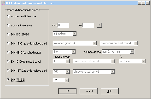
Tolerances according to DIN 7715 part 5 for elastomere parts has been added to the variety of selectable tolerances.
GEO2 Pre-defined bodies of rotation
GEO2 calculates mass moment of inertia of any rotation body from the cross-section. For ball, cylinder, ball with bore, hollow cylinder, cone, frustrum, frustrum with bore, annulus and ellipsoid, input was simplified by entering only diameters and height instead of coordinates of rotation profile.
GEO2 - Draw cross-section of rotation
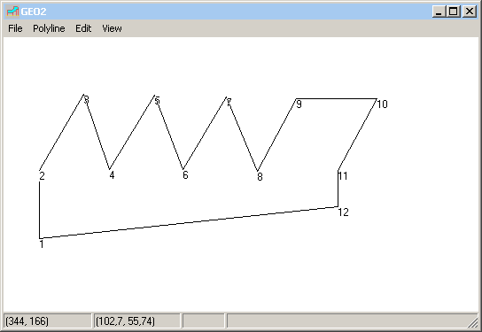
As alternative to input of the coordinates, you can now draw the cross-section of rotation area on the screen.
GEO2 Full Section Drawing
Instead of half-section, production drawing shows now full section of the rotation body. Because the area of full section is double value, table with results lists now both, rotation area (Arot) and section of the body (Axy).

FED2+ Rectangular wire reduces bending stress in loops
Normally, the maximum stressed area of a tension spring is the transition fillet of the coils into the loop with bending stress and tension. Therefore, the Quick3 view shows the Goodman diagram of bending stress instead of the Goodman diagram of shear stress. But there is one exception: If the extension spring is made of rectangular or elliptic wire, stress may be higher in the coils than in the transition radius to the loops. In this case, Quick3 and Quick4 View are now drawn with the Goodman diagram of shear stress.
SR1 Differences with old calculations
If you open old calculations with a new versions of SR1 or SR1+, maybe you get error messages like "mzu<0.8P" and warnings "mzu < 2P" and "SG < 1.2". In the old VDI 2230-1:2003, calculation of minimum engaged thread length considered a non-bearing thread length of 0.8 thread pitch. In the new version of 2014, non bearing thread length "mzu" can be self-defined (recommended 2 * P). In earlier versions of SR1 and SR1+, you could input non-bearable thread length, only the term "mzu" is new. And input of 0 caused no warning.
The warning "SG < 1.2" is a warning only, because VDI 2230 recommends a minimum safety of 1.2 for static radial load FQ and 1,8 for alternating FQ.
Configuration 3D -> 2D DXF-IGES

3D drawings are displayed on screen in a configurable xyz coordinate system, for DXF or IGES export, however, 3 dimensional with x,y,z coordinates. Now, you can configure at "File->Settings", if you want to export 3D drawings with xyz coordinates, or as 2D drawings in a coordinate system (same as the screen drawing). This option makes sense if 3D drawings are included in 2D drawings (production drawing, Quick3 view).
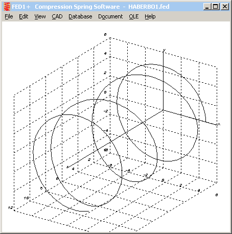
Table with error messages in Quick View

If too many error messages, overlapping with regular printout could occur. To avoid this, text height of error messages is reduced now, if too many error messages.

Floating Licenses: use various releases together
If you update your software, and want to use both, old and new version for a transition period, you simply have to rename the old program file, i.e. wsr1.exe into wsr1old.exe. All program files must be in the same folder, i.e. wsr1.exe with the new version, wsr1old.exe with the old version, and wsr1ger.exe with the German version. If you want to use different database files with the different versions, you have to define different "Start in" folders with different configuration files (wsr1.cfg)