
SR1 New Release of VDI 2230
VDI released a new VDI 2230 in December 2014. Traditionally, one must firstly troubleshoot a new VDI 2230, before implementing the changes in SR1+ (as it was in VDI 2230:2001, later replaced by VDI 2230-2003). Until now, new modified material data have been checked and taken into material databases of SR1+, and application examples in annex B verified with SR1 results. Application examples B1 .. B5 of VDI 2230-1:2014 are delivered with SR1+ in the files 1_2014.SR1 .. 5_2014.SR1 now. Other changes of the new VDI 2230 have not yet been validated and implemented. Maybe more in the next info letter.
Thread strip safety: that an addendum of 0.8 P is not enough for chamfers of bolt and nut thread, is in SR1 already considered: At Edit->Load, you can enter length of non-bearing thread length.
In VDI2230-1:2014, meff is now calculated without addition of 0.8P, and newly defined mges = meff + mzu:
mgesmin = meffmin + mzu (with mzu = 2P, Index min = with thread tolerance)
Old VDI 2230 of 2003 assumed thread strip for internal thread only. New release admits that the bolt thread can strip as well.
All these has been indicated by Mr. Dose more than 12 years ago, but VDI 2230 ignored his improvement suggestions completely. What a shame that he died meanwhile (www.hexagon.de/dose/).
In SR1, modified formula for meffmin according to VDI2230-1:2014 without 0.8 P is used now. VDI 2230:2014 defines "mzu = 2P". In SR1, you can input "mzu", suggest button sets mzu = 2 P for DSV with nut, and mzu = 3P for ESV with dead hole, because most bolt standards define a non-bearing thread on a length of 2 P.
We also wanted to implement new formulas in chapter 5.5.5.2 "Bolt thread critical". But this was stopped by an undefined factor "RS3" in formula (211).
And why non-bearing thread length should be mzu = 1.2 P for bolt thread critical (213), but 2.0 P for nut thread critical (209), is nowhere explained.
In the following, I have listed some other errors that I found until now:
Errors in VDI2230-1:2014 Table A9:
1. Limiting surface pressure of 42CrMo4: 300 N/mm², I assume that it should be 1300 MPa.
2. GJL-250 has material number 0.6025, and material number 0.6020 belongs to GJL-200.
Errors in VDI2230-1:2014 Appendix B Application Examples
1. B1.2: R2: minimum clamp load required is 1000 N, and not 103 N.
2. B2.2: R0 (rough determination d): column 3 of table A7 at 100 000 N is not bolt size M16, provided the strength grade 10.9. It is M18 according to table A7.
3. B3 Drawing: Minimum bolt diameter should be d0. But in the drawing, minimum bolt diameter is smaller than d0.
Or the drawing is correct, and error is in dimensioning of d0. I assume that d0 is minimum external bolt diameter, and the first section of the bolt (dimensioned with d0) is 27 mm.

4: B4: Faulty design: fitting surface of the bolt does not meet interface between connecting rod and connecting rod bearing cap. Bolt must be assembled upside down (bolt head at connecting rod side) or bolt dimensions have to be modified.

Apart from that, I would recommend a fine thread for this application.
5. B5 R11: Insufficient length of engagement: hexagon socket head bolt M20x60 allows chamfer and non-bearing thread on a length of u <= 2P according to EN ISO 4762:2004. Together with 1*P for the inner thread, length supplement to the length of engagement is then "mzu" = 3*P. With meffvorh = mvorh 3*P = 17,5mm follows that: meffvorh < meff.
This means that a detailed calculation as per section 5.5.5 is required.
The calculated value for nominal diameter of d, D, D2 and d2: meff = 18,2mm. Results with thread allowance of internal thread and bolt:
6H/6h: meffmin=18,6 mm
6H/6g: meffmin=18,9 mm
6H/6e: meffmin=19,2 mm
And meffvorh and mvorheff means the same in R11 of B5 ?
SR1 - Material Database
Table A9 in VDI 2230-1:2014 with materials for bolted components has been modified and extended. We created a new file mat_p_2.dbf with material data of VDI2230:2014 table A9. So you can choose now between 3 material sources when entering clamping plate material data:
MAT_P_2.DBF with table A9 of VDI2230:2014 (40 materials)
MAT_P_1.DBF with table A9 of VDI2230:2003 (26 materials)
PRESSUNG.DBF with tables of VDI2230:1987, VDI2230:2003, VDI2230:2014 and other materials from literature and by customer-defined material data (260 materials)

We did not overwrite old material data with new material data, because this would change calculation results, if you open SR1 files with earlier calculations.
In the PRESSUNG.DBF, you find equal materials with different material data from different sources.
If you want to update former calculations with new material data, without selecting materials from MAT_P_2.DBF for each calculation, you can overwrite MAT_P_1.DBF with MAT_P_2.DBF.
SR1 Thread Allowance

Calculation of thread tolerances was improved - in precision as well as in window design. At "Edit->Bolt" and "Edit->Nut", thread tolerances are displayed and updated when you select allowance class.
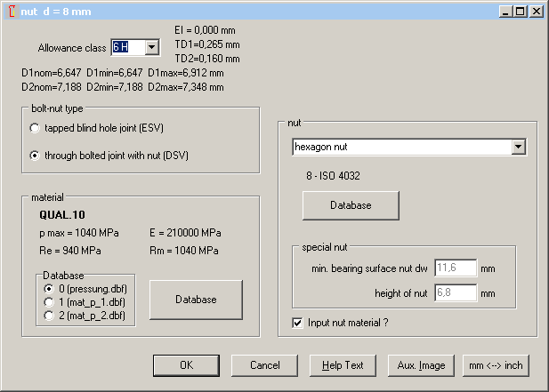
Allowance class "6f" and "4f" have been added for bolt thread. Allowances "es" and "EI" as well as tolerances "Td and "TD1" are now replaced by the exact table values, instead of calculated values from the formulae of ISO 965. Tolerances for threads in inches and other sizes beyond the ISO 965 tables are calculated as before.
In SR1 you can consider thread tolerances for calculation of the assembly preload FM and tightening torque MA (configure at "Edit->Calculation method"). VDI 2230, however, uses nominal dimensions without tolerances. This was set as predefined option now.
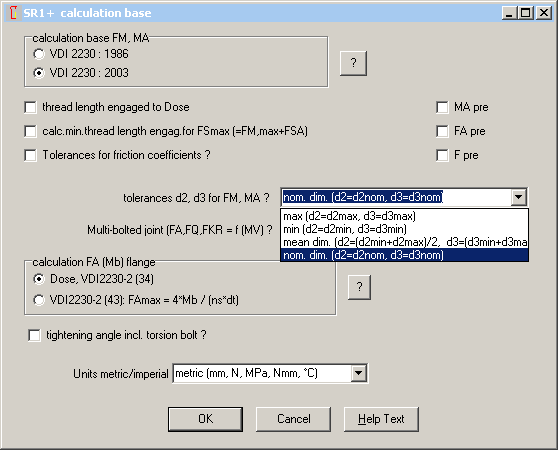
Thread tolerances are also used for calculation of minimum thread strip safety.
In SR1, preset for allowance class of external thread was changed from "6h" into "6g", according to recommendation in ISO 965-1. Preset allowance class of the internal thread remains "6H".
If you want to change preset values when starting a new calculation, enter desired values and save with file name "NULL". NULL file is loaded automatically at program start.
ZAR1+, ZAR2, ZAR3+, ZAR4, ZAR5, ZAR6: Material Data and Hardness Conversion

Brinell hardness HB is input field at material data. Now you can click into "?" button to pop up a hardness conversion window (known from HAERTE software) and enter and convert hardness in Vickers, Rockwell or tensile strength.

The hardness conversion software "HAERTE" is no longer offered as separate module, now you can use ZAR software for hardness conversions.
ZAR1+: calculation of effective face width
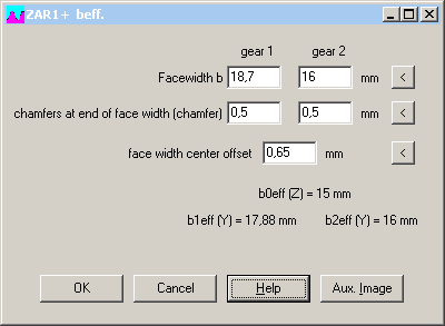
If different face width of pinion and gear, flank load-bearing capacity with safety against pitting is calculated with overlapping face width. For full lap, b0eff is the face width of the smaller gear. Chamfer width must be subtracted. If width center is different between gear and pinion, overlapping width must be calculated. For calculation of tooth root strength, full face width "b eff (Y)" is used for calculation, if the distance to the overlapping width is less than 1 * module. In the new version of ZAR1+, b0 is no longer an input value, because effective face width is calculated. In a new input window you can enter face width, chamfer width, and face width center offset.
ZAR5: calculation of effective face width
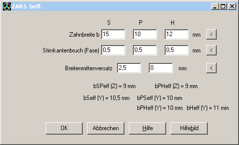
Same as in ZAR1+, click now into ZAR5 beff button to input face width, chamfer width and center offset. ZAR5 calculates beff(Z) used for pitting safety, and beff(Y) used for tooth root stress.
ZAR1+: Lubricant data

If you click the ".." button at viscosity input, you get a pop-up window for input of additional lubricant data.
ZAR1+ Side view profile
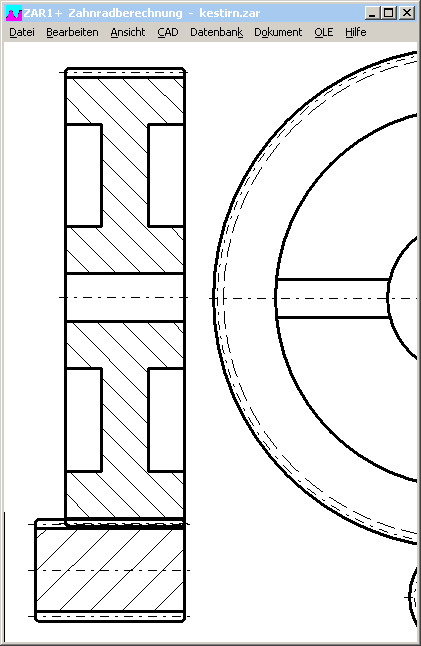
Pinion and gear wheel is drawn in profile side view, considering 45° chamfers and face width center offset. If inner diameter di > 0 was defined, ZAR1+ draws inner circle with ribs. Side view profile is also drawn in Quick4 view.
ZAR1+ View Strength

New output window contains results of strength calculation, main formulas and coefficients K, Y and Z on one screen. This screen is shown now after input of strength or power or material.
ZAR1+, ZAR5: Comparison ISO 6336 and DIN 3990
I found more differences as expected, however for special pairs only:
ZB for small number of teeth and low contact ratio:
ZB according to ISO 6336 is much higher than to DIN 3990. According to ISO 6336, ZB is undefined for epsilon alpha<=1 at epsilon gamma>1. And ZB cannot be calculated if epsilon alpha<=1.
For internal gears, I found differences in calculation of tooth form factor YF and stress correction factor YS. Whereas DIN 3990-3 says that for the fillet radius rhoF the half tool radius rhoFP/2 may be used, because the pinion cutter would generate a smaller root fillet, ISO 6336 calculates a fillet radius rhoF that is much bigger than rhoFP. This results in a stress correction factor SF half as in DIN 3990, and finally double safety against tooth root fracture.
But for external gears, factors YF and YS according to DIN 3990 and ISO 6336 are equal.
ZAR1+, ZAR5: ZL, Zv, ZR, ZW
In earlier versions of DIN 3990, lubricant film factors ZL, Zv, ZR were calculated separately for pinion and gear. Now there is left only one factor for the gear pair, where SigmaHlim of the softer material is used for calculation.
ZAR1+ Dimensions with tolerances
A new output window lists all dimensions and tolerances (nominal, max, min dimension) on one screen.
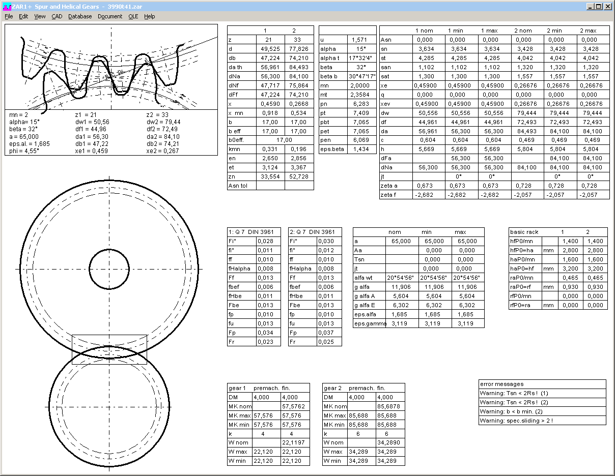
ZAR1+, ZAR1W, ZARXP, ZAR5: ball/pin diameter in tooth drawing

At "View->Tooth", measure circle diameter has been added to the tooth gap drawing. But only for spur gears it can be drawn as circle. For helical gears, it is drawn as ellipse, because the teeth are drawn in transverse profile, but the pins and balls lay beveled (in normal profile).
WN2,WN4,WN5,WN10: View tooth with measuring pin

New in all of the involute spline programs is the tooth gap drawing, known as in ZAR1+ and ZAR5, together with the measuring circle of the pin at "View->Tooth" menu. So you can check if available pins can be used. Or if a flattening pin has to be used.

ZAR5 Torsional backlash
ZAR5 printout lists torsional backlash in mm for gear pairs sun-planet and planet-ring gear. Total backlash input/output between driving shaft and driven shaft is listed in degrees. Example: input: sun, output: carrier, jt in: 10°, jt out: 1°. Backlash is 10° at the driving shaft with blocked driven shaft and 1° at the driven shaft with blocked driving shaft. Backlash of the driving shaft is backlash of the driven shaft multiplied with transmission ratio(for speed reduction gear).
jt output = jt input * n output / n input
Normal backlash jn and radial backlash jr have been added in the printout of ZAR1+ and ZAR5.
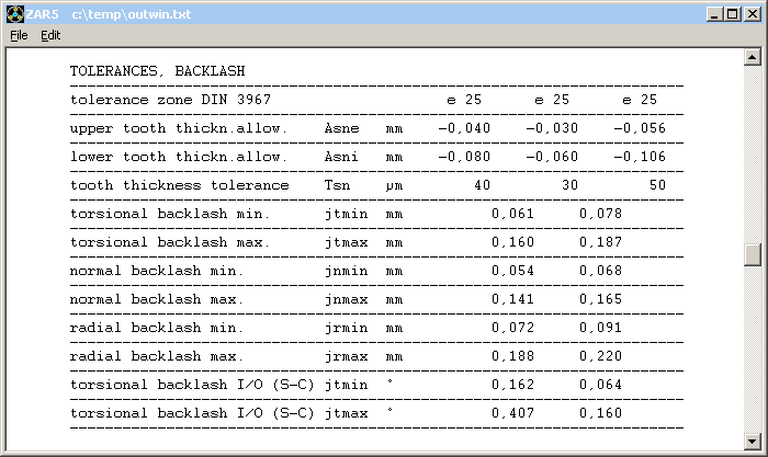
ZAR1+ Printout: Mass and mass moment of inertia added
ZAR1+ Printout: Normal backlash jn and radial backlash jr added
FED6 Quick4 View

New Quick4 View contains tables with coil data of the spring sections, tables with spring load, spring length and travel, result tables , spring drawings, load-extension diagram, spring rate diagram and buckling diagram on one screen in an A3 drawing frame.
FED1+, FED6: Tolerances
For cold-coiled springs, the program calculates tolerances according to EN 15800, and for hot-rolled springs the tolerances according to DIN 2096. The coefficient kf was not correct in the calculation to EN 15800, this was fixed now.
kf = - (1 / (3*n²) + 8 / (5*n) + 0.803
The sign of the first term was not correct. kf is used for tolerances of load and spring length.
AL0 = af*kf*Q/R
AF = (af*kf + 1.5*F/100)*Q
The error is rather small, not even detectable when comparing with the diagrams in EN 15800: for coil ratio w=9, maximum deviation is 0.8%, for Dm/d > 9 less than 0.8%. If Dm/d is only 4, maximum deviation is 3.5%.
If spring dimensions are beyond the defined limits, you get a warning message:
Scope of EN 15800:
rod or wire diameter: 0.07 mm <= d <= 16 mm
coil diameter: 0.63 mm <= D <= 200 mm
length of unloaded spring L0: <= 630 mm
number of active coils n: >= 2
coil ratio: 4 <= w <= 20
Scope of DIN 2096:
rod or wire diameter d: 8 bis 60 mm
external coil diameter De: <= 460 mm
length of unloaded spring L0: <= 800 mm
number of active coils n: >= 3
coil ratio w: 3 bis 12
If spring dimensions are beyond scope, you get warnings. Even if you configured "Hide warnings". Select self-defined tolerances instead of quality classes to remove the warnings.
Command line mode calculations in batch mode
Every HEXAGON calculation program can also be used in command line mode. In this mode, you can perform a huge number of calculations in short time, import/export input data and results from/to FEM or other programs. Example with Excel and SR1+:
---
Sub run_calculation() 'start command line program
Dim appID As String
appID = Shell("c:\Hexagon\WSR1.EXE path_and_filename.sr1 /I") 'starts SR1+, calculate and save results in TEST.txt - in the same folder than Excel file
End Sub
---
Do you use your HEXAGON Software in command line mode? Please describe your application mailto:fritz.ruoss@hexagon.de
If you offer engineering services (calculations with HEXAGON software in batch mode together with FEM or other programs), please let me know, so we could link your info site in hexagon.de.
WINLIFE is a program for complex fatigue strength calculations of components by Steinbeis transfer center for traffic and automotive engineering, directed by Professor Willmerding. The module "Gears" uses ZAR1+ in command line mode for fatigue strength calculation. Import and export of data is handled by means of EDI files.
www.stz-verkehr.de
ZAR1+ can also be linked with the Mesys software for shaft systems. Data exchange via zar files for input data and txt files with results.
www.mesys.ch