ZAR1+ Flank Tolerances according to ISO 1328 or DIN 3961

A new international standard ISO 1328 is available for tooth flank tolerances. Until now, tooth flank deviations had been calculated according to DIN 3961. Now, you can configure at "Edit -> Calculation method", if tooth flank tolerances should be calculated according to DIN 3961 or ISO 1328.

Tooth thickness tolerances are calculated according to DIN 3967, as usual. Flank tolerance class and flank thickness tolerance zone are listed separately now.
ZAR1+ Hide Warnings
At "Edit->Calculation Methode" you can configure that warnings are not listed in printout and Quick views.
ZAR1+ dFamin and dFamax instead of dFa
Form diameter (at chamfer tool) is now calculated with tolerances, minimum and maximum value of dFa are printed now instead of nominal value of dFa.
ZAR1+ Specific Sliding
A new diagram shows specific sliding of tooth contact along the pressure path g alpha.

This diagram is printed with Quick3 and Quick4 view, too.
ZAR1+ Animation

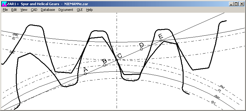
Now you can define start and stop angle of the animation. Buttons for default settings A-E, A-C and C-E set start/end angle to A, C, and E. Because rotation of gear 1 is defined clockwise (in negative mathematical direction), start angle is higher than end angle in this case.
ZAR1+ Tooth Thickness Tolerance
A new true-scaled chart makes clear the coherence of tooth thickness tolerances Asne1, Asni1, Asne2, Asni2, Tsn1, Tsn2, backlash jmin and jmax, nominal profile shift coefficients x and generated profile shift coefficients xE.

ZAR1+ Load Spectrum Table in Quick4
If a load spectrum was defined, table with load cycles and torque will be printed within Quick4 view now.

ZAR1+ Tooth Contact A,C,E
Tooth contact at action points A, C and E can be displayed now directly, see menu "tooth contact".

ZAR1+ Tooth Contact Varia
New buttons A, C, E for tooth contact in predefined action points. C is the contact point on the operating pitch diameters, where specific sliding is 0. A is the begin of tooth contact and E is the end of tooth contact along the pressure path (with gear 1 driven, clockwise rotation).

Points B (= E – pet) and D (= A + pet) have been added in the new version. But B and D are drawn only if contact ratio epsilon alpha (=g alpha/pet) larger than 1.05. If epsilon alpha = 1, B and D are equal with A and E. If epsilon alpha is less than 1, B and D are beyond of A and E.
ZAR1W – New Software for Dimensions of Spur and Helical Gears
Soon we can offer a new software ZAR1W for calculation of dimensions and tolerances of spur and helical gears.
So there are now three calculation software for spur and helical gears available. The most complete is ZAR1+, whereas ZAR1W and ZARXP provide subsets of ZAR1+ only.
ZAR1+ calculates dimensions and strength of a gear pair. Applicable for design engineers and manufacturers of gearboxes and gear wheels.
ZAR1W is predestinated for manufacturers of gear wheels.
ZARXP is the best to manufacture replacement gear wheels from an existing gear, if no drawing is available.
Comparison of ZAR1+, ZAR1W and ZARXP
|
Dimension |
Tolerances |
Strength Calculation |
Protuberance and chamfer |
|
|
ZAR1+ |
Gear pair |
Yes |
Yes |
Yes |
|
ZAR1W |
Gear wheel |
Yes |
No |
Yes |
|
ZARXP |
Gear wheel |
No |
No |
No |
ZAR5 Tooth Flank tolerances according to DIN 3961 and ISO 1328
Same as in ZAR1+, you can configure at "Edit->Calculation Method" if tooth flank tolerances shall be calculated according to ISO 1328 or DIN 3961.

And you can configure if pin/ball diameter and number of teeth measured shall be defined by input, or calculated automatically.
ZAR3+ Animation - Input of Start Angle and End Angle

Same as in ZAR1+, start angle and end angle for animation can be modified now.
SR1 – Prevailing-Torque Type Hex and Hex Flange Nuts
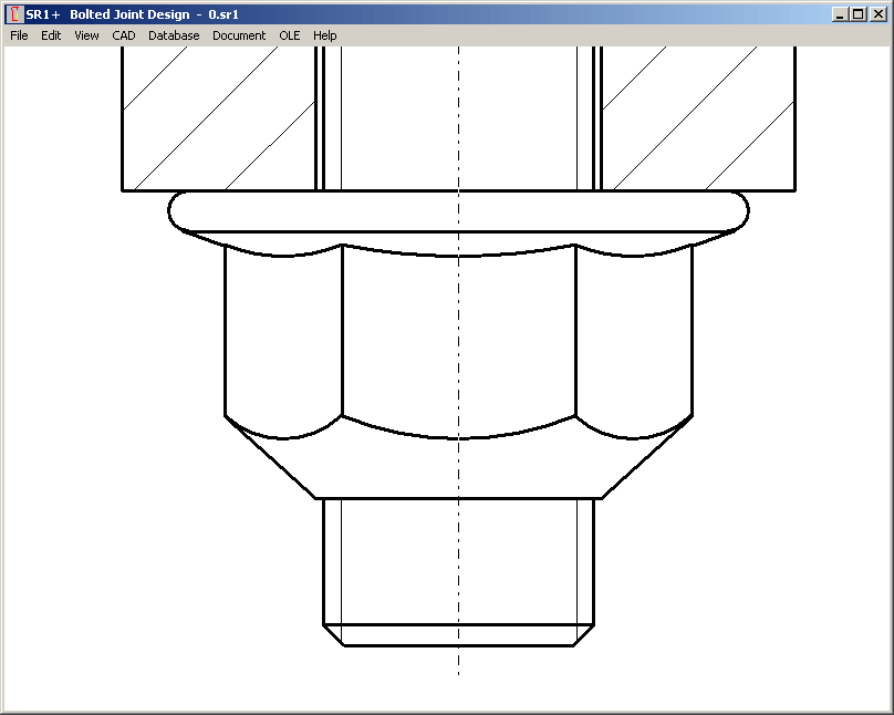
Prevailing-torque hex nuts to ISO 7042 and prevailing-torque hex flange nuts to ISO 7044 have been added in SR1 and SR1+.

Additional torque by friction and additional shear stress has to be considered in this case. SR1 calculates higher tightening torque and reduced clamp load for equivalent stress. If you select a prevailing-torque type nut from database, friction torque is set as MA pre, and MA pre option will be set. If you later use a standard nut without prevailing-torque, you have to reset MA pre to 0.

HPGLMAN, DXFMAN File Open (Table)
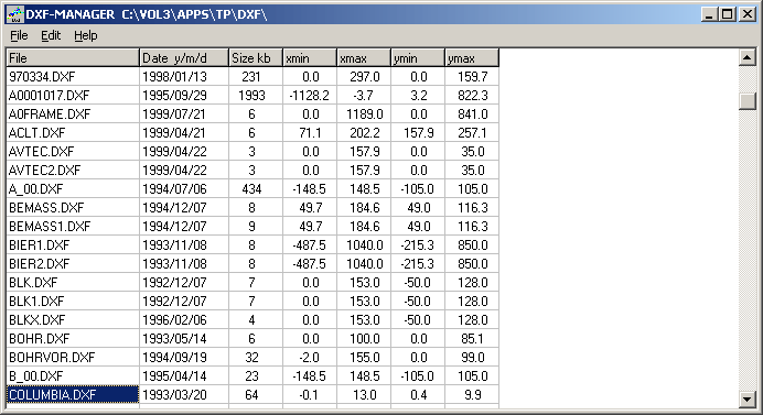
Similar than in the calculation software, HPGL-Manager and DXF-Manager got a preview with table (drawing date and drawing limits). Selected drawings are displayed in the graphic window. If you search for a drawing and do not know the filename, use preview to find it.


FED5 – 3D-Polyline

3D center line of the conical compression spring is now created as 3D polyline if you save it as DXF file. IGES format has no direct polyline definition, so the 3D centerline remains composed of many small lines. Resolution can be configured at Edit -> Calculation Method.