SR1+ and VDI 2230 part 2
VDI released in November 2011 a new draft standard VDI 2230-2 for multi-bolted joints. It describes how to calculate the load of the mostly stressed bolted joint from multi-bolted joints.
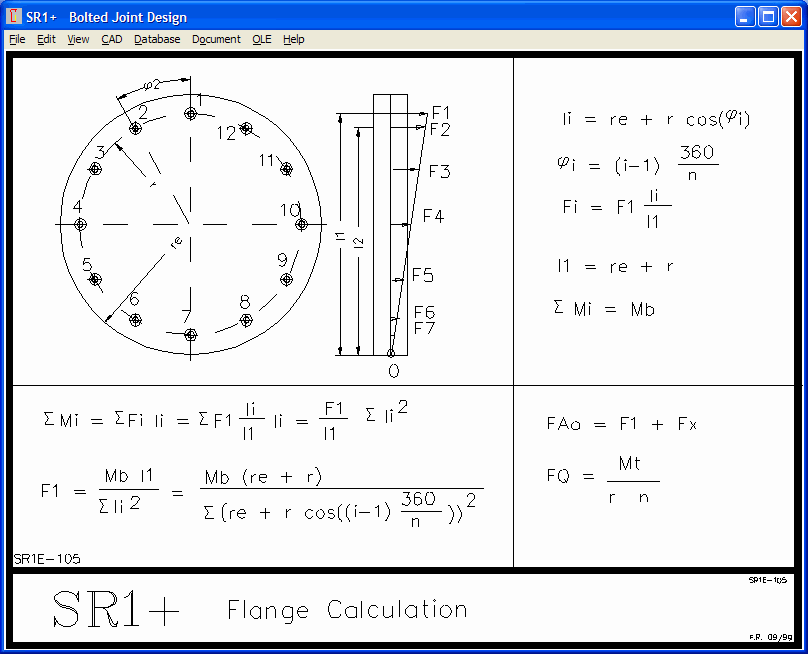
SR1+ provides calculation of the mostly used multi-bolted joint, a circular flange, since 1999. Now we can compare if calculation according to new VDI2230-2 is identical with the calculation according to Dose used in SR1+ since 1999. Dose formulas are described in auxiliary image SR1E-105.
Circular flange with multi-bolted joints is described in chapter 6.3.2 of VDI 2230-2. Calculation of axial load FA on the most stressed bolted joint from a bending moment on the flange is described in chapter 6.3.2.3, formula (34):
FA(M)max = Mz * xmax / Σ xi˛
This formula seems to be equal with the formula according to Dose used in SR1+. But it seems that the x coordinates are referenced to the flange center. However, according to Dose formulas, point 0 is the outside diameter of the flange.
VDI 2230-2 provides another approximation equation:
FA,max = Mz/(ns*dt) * (FB*dt/Mz + 4) (43)
leads to
FA,max = FB/ns + 4*Mz / (ns*dt)
Amount of bending moment according to this formula (FB=0):
FA,max = 4*Mz/(ns*dt)
Now we have added this formula (43) from VDI 2230-2 in SR1+ as alternative calculation method. It can be configured at "Edit-Calculation Method" or at "Edit->Flange". In the input window for the flange data, you can now switch between the two calculation methods to see how it influences the results.

There is even a possibility to get the same result: set flange diameter de=0, and you get equal results for Dose and VDI 2230-2 calculation .
What is the right calculation method now? According to VDI 2230-2, bolt loads FAo and FAu are calculated like bearing pressure on supports of a hinge-mounted beam. Dose calculates bolt loads FAo and FAu from the bending moment on a beam with one bearing pressure support on the the flange border (see point 0 in auxiliary image). In Dose calculation, flanges are assumed as rigid, and bolted joints as elastic. VDI2230-2 calculation is appropriate for rigid flange and rigid bolted joints on elastic counter flange. Which calculation method is better? This depends on how elastic are the components assumed as rigid. Calculation according to VDI2230-2 results in higher loads for the mostly-stressed bolted joint because of the shorter lever arms, so you are on the safe side if you favor this method.
Auxiliary image SR1E-105 was completed with the equation (43) for FAo according to VDI 2230-2.

SR1+ Quick View with Flange Data

At "Edit->Flange" you first have to define if loads on bolted joint should be calculated from flange load in the new release of SR1+.

If you select this option, flange dimensions and load is displayed in Quick View, and considered if you open sr1 files at "File->Open". In earlier versions, bolted joint loads from flange have been calculated in the flange input window only, and could be modified at "Edit->Load". If you want to modify the calculated loads in the new version at "Edit->Load", you first have to set "no flange" at "Edit->Calculation Method" or "Edit->Flange".

SR1 – Twelve Point Flange Bolts
Twelve point flange bolts have been added into SR1 and SR1+.

Unfortunately, there exists no ISO nor EN standard for this bolt type.

Dimensions according to US standards NAS624 until NAS644 (National Aerospace Standards) and Military Standard MS21250 as well as metric sizes M6 until M20 from Darling Bolt can be selected from database.

FED5 – Spring Energy

Spring energy W01, W02 and W0 has been added to the spring energy diagram.
FED1+, 2+, 3+, 5, 6, 7, 8, 11: Restrict Spring Materials from Database
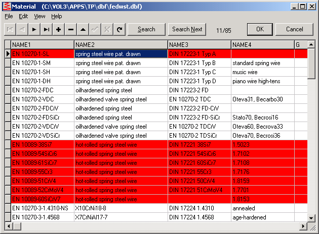
Because of several updates over the years, number of spring materials has grown to 85 now, and selecting the right material may be confusing for occasional users. To delete records from the database is no good solution, this causes problems on loading older calculations and with later updates. But you can red-mark unwanted materials at Database->fedwst.dbf by means of "-" button (do not execute "Edit->Pack" after that, else it will be deleted physically). New versions of the spring programs do no longer list red-marked materials at "Edit->Material".
Command Line Mode (Batch Mode)
Every HEXAGON program can be used to perform calculations in the background, controlled by self-written programs. This enables you to perform many calculation in short time for variants, FEM calculations, or complex systems. For input, simply modify the input file (text format). Output can be the printout as text file, or a graphic in DXF, IGES or TXT format. Example:
C:\hexagon\fed1\wfed1.exe c:\hexagon\fed1\train\actual.fed /i
FED1 reads file actual.fed, performs spring calculation, creates result file actual.txt, then exits.
Some programs created incomplete result files in the past, this was updated now in GEO2, GEO4, WN2, WN10, ZAR1, ZAR2, ZAR3, ZAR4, ZAR5, ZAR6.
Windows 8 Released
HEXAGON programs (32-bit versions since 1999 and 64-bit versions of 2012) can also be installed as App under newly released Microsoft Windows 8 operating system.