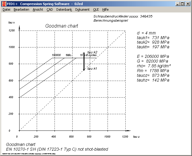
FED1+, 2+, 3+, 5, 6, 7, 9: Life Cycles
Number of life cycles are calculated from Goodman-Diagram. Parameters are material, shot-peening, pretension and shear strength variation between two loads (tau h).
Dynamic safety is S = tau h perm / (tauk2 - tauk1)
Static safety is S = tauk2 / tau perm
For high pretension and low stroke, static safety may be smaller than 1, but dynamic safety and life cycles may be very high. Of course, calculated number of load cycles is not valid for a spring with static overload (Error: tauk2 > tauoz). Spring may be break down with the first stroke.
Spring programs now suppress output of load cycles, if tauk2 > tauperm.
For the example above, spring would bear about 10 million load cycles, if not the permissible shear stress would be overridden (tauk2>tauo).
Also buckling of a spring reduces the calculated number of life cycles. First solve buckling of the spring, else calculated number of load cycles is not realistic.
FED1+, FED2+, FED3+ Export dbf, xls

As export function for spring parameters and calculation results, dbf format is best choice for interface with other programs (PPS, database, machine control). At "File->Export dbf,xls" you can now also generate a MS-Excel file as alternative. Field names, field structure and field numbers are firm, field names and sequence similar than in text printout (View->Printout).

ZAR1+, ZAR5 - Virtual Number of Teeth zn
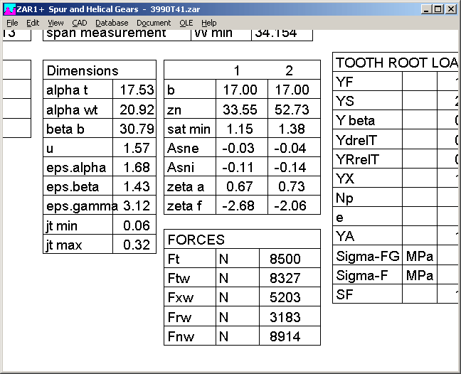
Virtual number of teeth zn has been added in Quick3 view. If you want to get a tooth profile drawing in normal section instead of transverse section, you can set helix angle ß=0 and replace z by the rounded value of zn.
New button "ß=0, z=zn" automates this conversion, also fixes tolerances and sets radio buttons to "kmn" and "a".
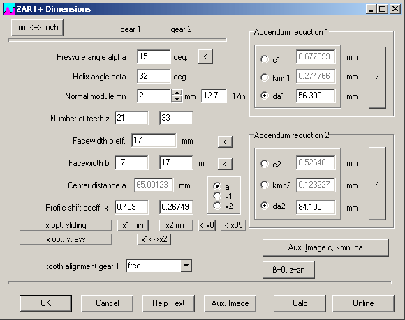
ZAR1+, ZAR5 Calculate Micro Gears
Very small gears (i.e. module < 0.1mm or diameter < 1.0 mm) can be calculated with ZAR software, if you pay attention to some settings:
1. Tolerance zone
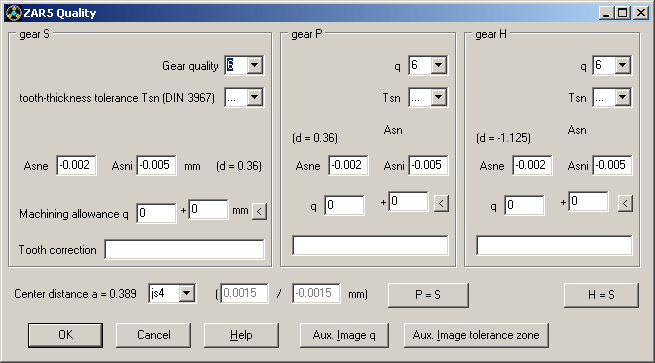
Tooth thickness tolerance to DIN 3967 depends on pitch diameter, minimum area is described 0-10mm. Realistic is 5 .. 10 mm. For a pitch diameter less than 5 mm, tolerances Asne and Asni should be entered individual.
Example: gear with module 0.1 and 8 teeth (d=0.8mm), tolerance zone e 25 gives Asni=0.042mm. For this case, tooth thickness tolerance would be more than tooth thickness itself (sn=0.019mm)!
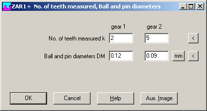
2. Pin and Ball Diameter
Pin and ball diameters must be adopted to micro dimensions.
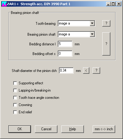
3. Strength Calculation
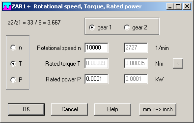
If you get error message "dsh=0!", go to "Edit->Strength->DIN 3990->Part 1" and set pinion diameter to tooth root diameter. Power in kW must be higher than 0.0001 kW (0.1W). Please consider that results of the strength calculation to DIN 3990/ISO 6336 are not precise for micro gears.
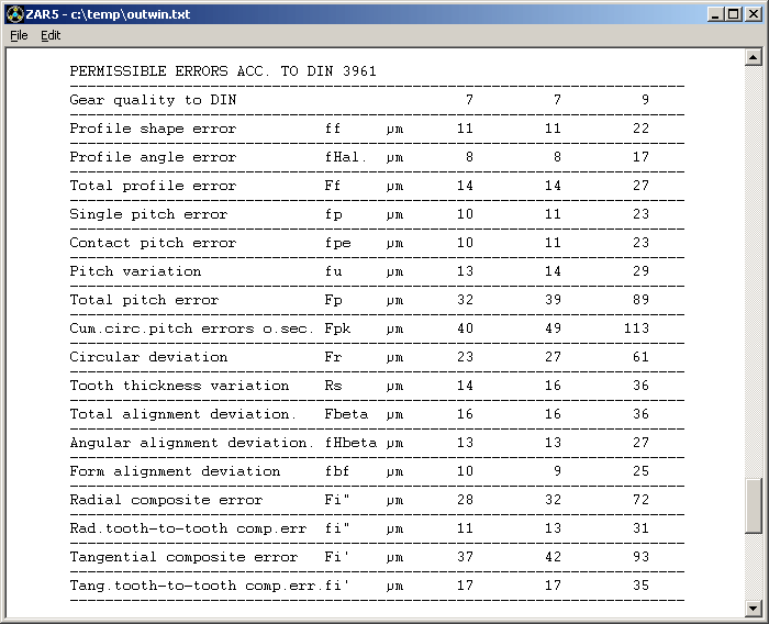
ZAR1+, ZAR5: Deviations according to DIN 3961
Deviations according to DIN 3961 are valid for modules from 1.0. New release of ZAR1+ and ZAR5 now suppresses printout of DIN 3961 deviations, if mn < 1.0.
ZAR1+ Settings for Profile Drawings Saved
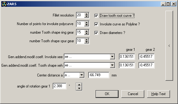
Settings for profile drawings (fillet resolution, number of points for involute curve, number tooth shape) are now saved together with the input data. This allows different individual settings for different gears.