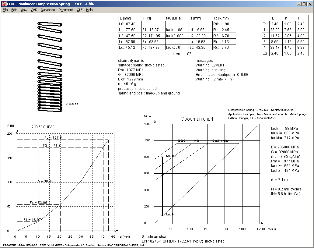
FED2+, FED3+, FED5, FED6, FED7: Quick 2 View

Like in FED1+, extended Quick view with spring drawing, load extension diagram and Goodman diagram on one page has been added to further spring programs.
SR1 - Safety for High and Low Temperature
When you define working temperature, safety factors change only in case that temperature lowers safety coefficient. It is assumed that bolted joint will be operated under defined working temperature as well as under reference temperature. SR1 calculates both safety coefficients and uses the lower one. One case had to be corrected: for low temperature (< 20°C), higher safety against pressure was listed, and reduced safety SG against sliding by FQ was not considered.
In table drawing, FKRmin, FV, FSmax are listed at working temperature. FM,max is listed at reference temperature as well as on working temperature.
Some descriptions have been renamed in SR1: FKmin into FKRmin, FKRo into FKRmax, FKRu into FKRmin.
When opening a file, graphic screen shows data of the machine element, mostly Quick View. Now you can configure at "File->Settings->Settings", which result screen should be shown after calculation or opening a file. As alternative to Quick View, you can configure production drawing, diagram, or drawing of the calculated machine element.

This new option is also very useful when you compare different variations and calculations at "File->Open (Table)".
Production Drawing: Modification index displays latest modifications
Table with modifications can show maximal 8 lines. If more than 8 modifications entered, only the last ones can be displayed in the drawing. Maximum number of modifications was enlarged form 10 to 25. All changes will be saved and can be listed at "Document->Modifications Info" and "Document->Modifications Printout". If you, for example, entered 25 modifications, production drawing lists only the latest 8 (Index "r" until "y") .

FED13 - Density and Weight
Weight of the wave spring is listed in printout now. Density of the material will be loaded from material database.
GEO1+, TR1 Configure Drawing

Now you can configure, if profile should be drawn hatched, and if gravitation axes should be drawn or not.

GEO1+, TR1 Print Coordinates with 3 digits
Dimensions of the profile are drawn with 3 decimal digits now.
GEO1+,GEO2, GEO3, GEO4, LG1, LG2: File Open (Table)

Preview function to compare and search data from earlier calculations are now also available in our GEO and LG programs.
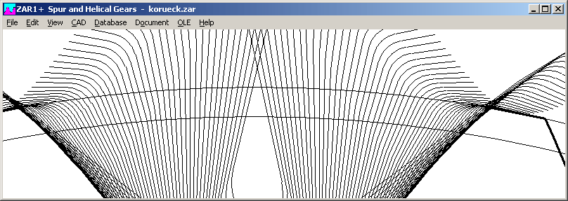
ZAR1+ Tip diameters "da th" and "da" with/without addendum reduction
For generation of tip diameter two cases can be differed:
Until now, printout listed "da th", "da0", and "da". "da th" is the theoretical tip diameter generated by cutting tool without consideration of tooth flank tolerances (nominal dimension). "da0" is the maximum tip diameter under consideration of the tooth flank tolerances. "da0" = "da th", if you selected tooth flank tolerance zone "h", or defined "Asne"=0. Tip diameter "da" is equal with "da0", if no addendum reduction was defined (kmn=0), else "da" is the input value defined at "Edit->Dimensions".
New version of ZAR1+ lists da0 only in case of addendum reduction (kmn1<>0 or kmn2<>0). Else, only tip diameter "da" and tolerance "A da" is printed. Tip diameter tolerance results from tooth flank tolerance for this case and is equal with tooth root tolerance.


Changes also in the tooth drawing and tooth contact drawing for kmn=0: tip diameter in tolerance center is drawn now (instead of maximum value). This is visible in the tooth drawing with tooth shape: tooth shape had cut into tip diameter, now it is equal with contour of tooth shape.

File problems if dot (.) in folder name
Files could not be opened if file path included one or more dots. Problem was solved now, dots in folder names no longer cause problems. Not allowed, however, are dots in the file name. File name must include one dot only, which separates file name and file extension.

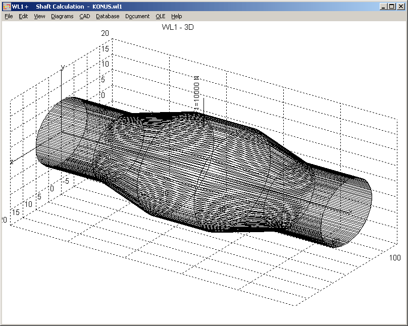
Shaft segments are drawn as polygon bodies for a better identification.
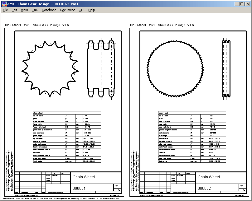
ZM1 - Production Drawing Chain Wheel 1 and 2

Production drawings of both chain wheels can be viewed and printed on one screen now.