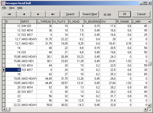

Thread length is loaded from database field L_THREAD of screw head database. If L_THREAD field is "0", SR1 now sets thread length lG = shaft length 2 * thread pitch. At "Edit->Bolt->Edit", you can modify thread length if you dont want to use database value.

Hexagon head bolts according to ISO 4017 have been added to database. Dimensions are equal than ISO 4014 hexagon head bolts. Only difference: thread length until head.
SR1 Thread strip length calculation with Rm,max instead of Rm (min)
For calculation of the minimum thread length engaged with consideration of tolerances, worst case for thread tolerances and maximum tensile strength of bolt is used according to VDI2230:2003. Because Rm_max is not defined in material database, SR1 used Rm (min) for calculation until now.
For bolts of resistance class 8.8 until 12.9, Rm_max can be calculated with "Rm_max = 1.2 * Rm_min" according to ISO 898-1. SR1 uses this conversion since release 16.2 for calculation of thread strip safety according to VDI2230 and to Dose. This leads to higher values for minimum required thread length engaged (meff). For lower resistance classes, tolerance may be higher. Take care: Calculation of thread strip safety to VDI2230 is valid only for the case that bolt is of higher strength material than nut thread.

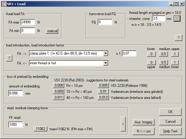
Since release V15.0 you can define length of chamfers and cone as non-engaged thread zone at "Edit->Load", for calculation of thread strip safety. Button "<" has set 1.0 * P for input. These value seems too low, at least for tapped thread joints (ESV). According to ISO 4014, "incomplete" thread is allowed until 2.0 * P from bolt end. New suggestion with "<" button for non-bearing thread length is now 3*P for ESV and 2*P for DSV (through-bolted joint with nut).
"m tr" is engaged thread length (thread depth or nut height less chamfer and cone).
Surface pressure between two clamping plates of large OD are no longer calculated from the real area, but from the area of the deformation body. A higher surface pressure will be calculated between large clamping plates because the maximum pressure is applied in the deformation area, depending on bearing diameters dw of bolt and nut and clamping length lk.

Dimensions of ISO 7089, ISO 7092, ISO 7093-1, DIN 7349 have been added to the washer database klemmstk.dbf.

The shear stress coefficient taub/Rm (= permissible shear stress / tensile strength) for calculation of thread strip safety according to VDI 2230 was modified in the material database pressung.dbf from 0.4 to 0.6. VDI 2230:2003 even suggests 0.7 but the calculated ratio of all material values in appendix A of the same standard are 0.6 or even lower. The equivalent coefficient BETA_M for calculation of thread strip safety according to Dose remains unchanged 0.4 and 0.5.
SR1 Calculation Method
Calculation of thread strip safety for the real bolt load FSmax is not defined in VDI2230, and not desired for some application, because mistake in bolt assembly process may lead to stripping of the nut thread instead of bolt fracture (expensive repair). Now you can hide calculation of thread strip safety for FSmax at "Edit->Calculation method".

Another new option is to use max, min, average or nominal thread dimensions for calculation of clamping load FM and tightening torque MA. Standard setting is d2=d2max and d3=d3max, these are also the nominal diameters for tolerance zone "h". For tolerance zone "g" or "e", FM and MA are a little bit lower. If you wish that FM and MA do not change with thread tolerance, you can select "nominal dimension". The two other settings (min and average) are of interest for tolerance analysis only.

Precision of thread tolerances from tolerance field was improved. Max, min, and average thread diameters of d2, d3, D1, D2 are listed on the printout now.
FED1+,2+,3+,5,6,7,8,11: Modifications in Spring Material Database
Permissible shear stress and tensile strength was modified for some materials. HEXAGON spring programs calculate tensile strength according to this formula:
Rm = Rm0 - DRM * log (d / DR0)
RM0, DRM and DR0 are database fields in "fedwst.dbf". "d" is wire diameter. Calculated value is minimum tensile strength. On stainless spring steels to EN 10270-3:2001, "1.4310" was renamed into "1.4310 NS", and "1.4310 HS" (with higher strength values) was newly added. And the increase of tensile strength by heat treatment (age-hardening) is considered now in the EN 10270-3 materials. This means: new (higher) database values are valid only if spring was heat treated according to the instructions.
Material modification of Rm for d=1mm
EN 10270-2 VDC + 5%
EN 10270-3-1.4310 (NS) + 5%
EN 10270-3-1.4568 + 14%
EN 10270-3-1.4401 + 11%
EN 10270-3-1.4310-S2 (Sandvik 11R51) + 10%
EN 10270-3-1.4310-S1 (Sandvik 12R10) + 5%
EN 10270-3-1.4568-S1 (Sandvik 9RU10) - 5%
EN 10270-3-1.4401-S1 (Sandvik 5R62) - 6%
EN 10270-3-1.4571-S1 (Sandvik 8R70) - 6%
EN 10270-3-1.4462-S1 (Sandvik SAF 2205) + 3%
EN 10270-3-1.4539-S1 (Sandvik 2RK66) + 1%
EN 10270-3-1.4310-S3 (Sandvik 13RM19) - 4%
EN 10270-3-1.4462-S2 (Sandvik Springflex) - 5%
EN 10270-3-1.4462-S3 (Sandvik Springflex SH) - 3%
EN 10270-3-1.4310-HS (neu)
Endurance strength values (Goodman diagrams) remain unchanged.
FED1+ Table Rm = f (d)

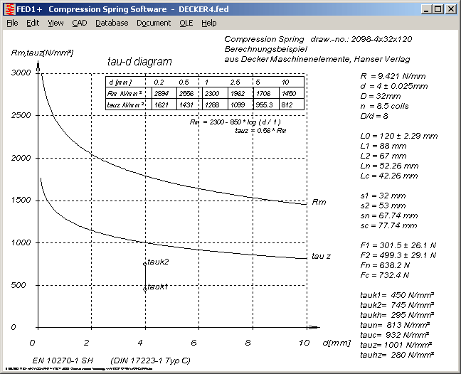
A table with tensile strength and permissible shear stress has been added to the diagram at "View->Stress->tau-d".
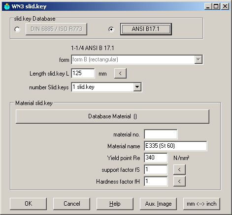
WN3 - Parallel Keys according to ANSI B17.1

Sliding keys according to US standard ANSI B17.1, square 3/32" up to 1-1/2" and rectangular 1-3/4" x 1-1/2" up to 7" x 5" can now be selected from database as alternative to metric keys to DIN 6885. German standard DIN 6885 for parallel keys is equal with ISO R773, JIS B1301 and BS 4235-1.

ZAR1+, ZAR5, ZAR3+, WN4, WN5: Tooth Profile Drawing with tooth root trochoide
Trochoide by tooth root radius was shortened (drawn only until begin of involute curve) to avoid intersection of involute and trochoide curve.