FED3+ Load-Travel Diagram in Polar Coordinates
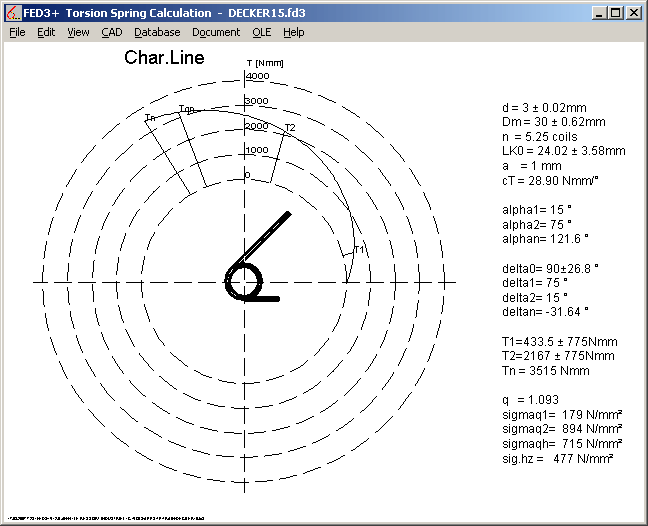
For torsion springs, x coordinate of load-travel diagram defines the spring angle. Diagram in polar coordinates may be more comprehensive for this spring type. As option, new version of FED3+ draws characteristic line of spring in polar coordinates now.

FED11 – Opening Width under Load
Until now, FED11 calculated only deflection of spring locks, but not opening width e under load. New version calculates opening under load, permissible opening width, and also generates a drawing of the loaded spring lock.
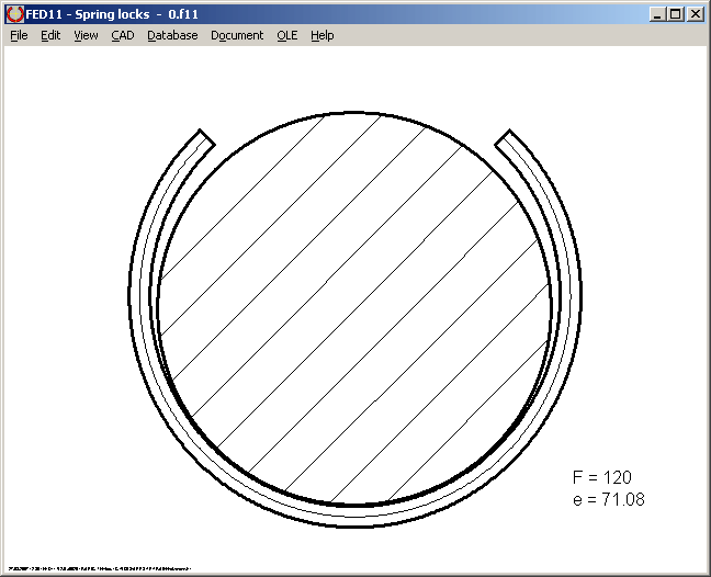
New Animation in FED11 simulates deflection of the spring lock between two freely definable loads.
New Version 2.0 of FED11 now considers stress coefficient q when calculating bending stress, safety and permissible bending stress. Analogue to FED3 (torsion spring), q has to be applied for dynamic load or static load against coiling direction. Spring locks for external application (shaft lock) are charged against coiling direction.
Sigma bq = Sigma b * q
q = 1 + 0.87 / w + 0.642 / w² (w = Dm / d)
New printed values are: opening width under load, permissible opening width, stress coefficient q, corrected bending stress sigma bq, wire length and weight.
If spring load is charged in closing direction (for grooves in bore), define spring load negative (Fx<0). For this case, stress coefficient is not applied, and opening width e decreases under load.
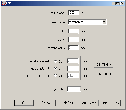
Because you can define round, elliptic, square or rectangular wire section, FED11 can also be used to calculate clamping bushes of any length.
Price of FED11 was increased from 160 EUR to 210 EUR
FED1+, FED2+, FED3+, FED5, FED6, FED7: Weight in Production Drawing
Spring mass m is printed together with wire length and pitch, if checked at "Edit -> Production Drawing".

FED13 – Fractional Number of Waves
Number of waves may now be fractional, 3.5 for example. Fractional number of waves (x.5) are required if you want to use FED13 for calculation of helical wave springs.
Other modifications in FED13: input data error check, and modulus of elasticity loaded from material database.
SR1+ Flange Calculation
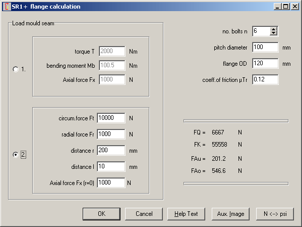
Load on flange may be defined by torque, bending moment and axial force, or by tangential and radial force on distance l and radius r, and axial force. It was not clearly defined that only tangential and radial force may be placed off-center, however axial force always defined central. Therefore, input field of Fx was placed after r and l, and description modified to "Fx (r=0)".
TOL1, TOL2 - Decimal Places
Digits after comma for input of dimensions and tolerances were fixed to 3 in TOL1. For use with millimeters, this is best choice. If the tolerance analysis software is used with inches, there are at least 4 digits after comma required. New versions of TOL1 and TOL2 provide configuration of decimal places at "Edit->Settings".
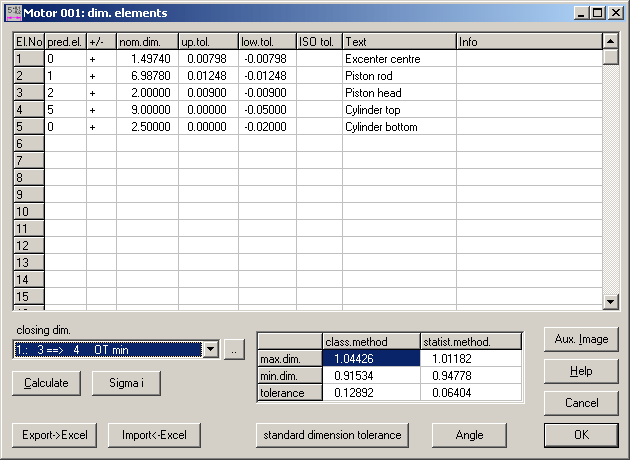
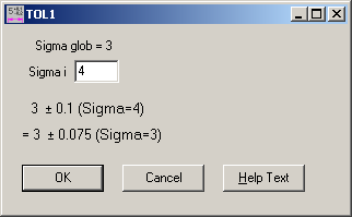
Sometimes, user ask if it would be possible to define different sigma coefficients for each dimension. It would be no problem to extend TOL1 with input of sigma for each dimension. But which sigma coefficient should be applied to the resulting tolerances? More clear from user's sight is to have all tolerances related to the same sigma. TOL1 provides a conversion function (Sigma i button). The conversion is simple:
Tolerance glob = Tolerance * Sigma glob / Sigma i
Example: ± 4 Sigma is required for dimension 3 ± 0.1. Sigma for all other tolerances is ± 3 (Sigma < glob). Tolerance is changed to ± 0.075, now applied to ± 3 Sigma.
± 3 Sigma signifies a reject rate of 0,26%, or one of 385 parts is bad. Reject rate for ± 4 Sigma is 0,0063%, or one of 16.000 parts is bad.
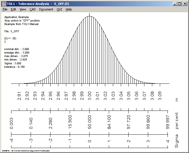
For the example, tolerance ± 0,075 is granted by 99,74% of a random sample. And 99,9937% of the random sample should lay inside the tolerance ± 0.1.
Problems with included points "." in folder name
Points in folder names caused problems when saving and loading files. New versions (since July 2007) allow one or more points in the folder name (i.e. "c:\www.hexagon.de\". Still not allowed are points in file names. Filename must include only one point, which separates file name and file extension.
When configuring temp path, there is a button "<" to set default Windows defined temp path.
If you choose HTML printout by Internet Browser ("File->Settings": Printout: check "Show output dialogue box", then external: select HTML Browser), HTML file is saved in temp path, then loaded by Internet Browser from temp path. Now it has been detected that Microsoft Internet Explorer generates file access error message for this case. If you choose another temp directory (i.e. "c:\temp", it runs without problems. Therefore, better do not configure the Windows default temp directory ("C:\Documents and settings\Username\Local settings\Temp\") .

Hint: Save License Contract as Document
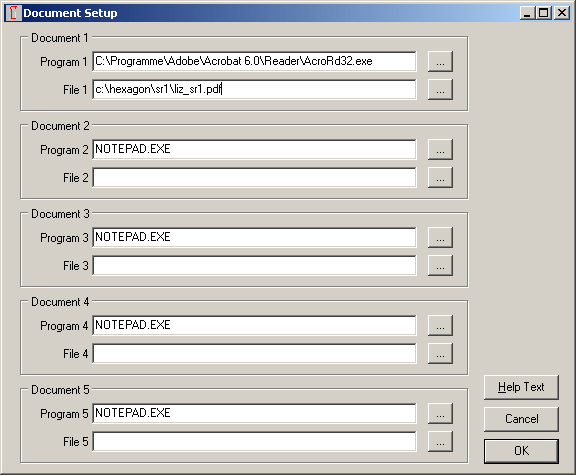
If you change or replace computer, you have to add new computer on license contract and to request new key codes. To avoid to loose license contract, scan and save as pdf file. Now go to menu "Documents -> Document Setup" in HEXAGON Software and select the pdf contract and the program that is used to open the pdf file. To save the link persistent, go to "File->Save As" and save under file name "null" together with default settings. If you already defined a "null" file, open it and define link to license contract file, then save back.
